There is a lot of talk online about 3D Printed part accuracy. Mostly what you will find being referenced by other 3D Printing services bureaus are the numbers that the machine manufacturers (OEM’s) give out in there user manuals. At Forerunner 3D Printing we wanted to put these numbers to the test and see what kind of accuracy we could really achieve with our equipment. 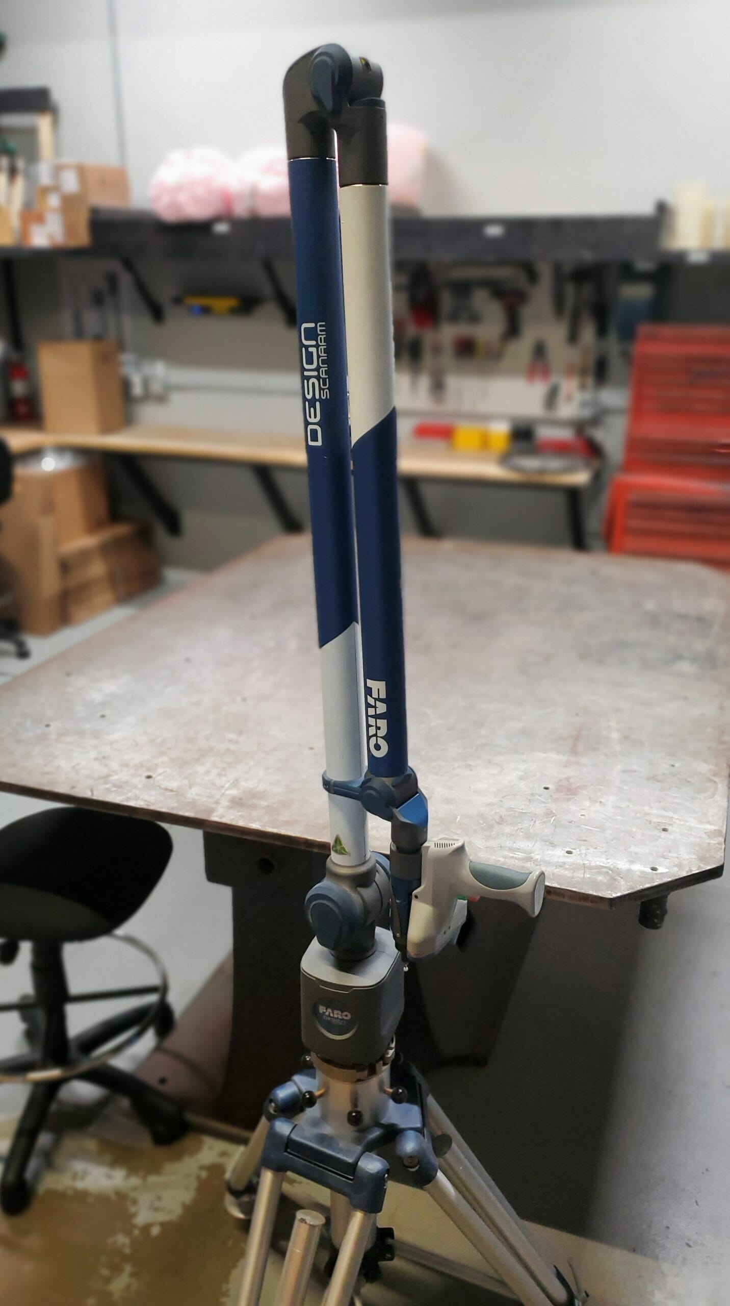 F3DP is equipped with a Faro Edge ScanArm system and Geomagics ControlX software (with assistance from DE, the engineering business unit in our company). The following are real inspection reports that were put together using our in house inspection equipment / process and parts that were built on our 3D Printers. To read a full PDF of each of the inspection reports shown on this page click on the accuracy heat map images below. Also, if you have a 3D Printing project that requires critical tolerances to be maintained, we offer additional in-depth inspection report services on 3D printed parts we produce for our customers, please inquire about this service when we are quoting your project. Before we jump into looking at inspection reports, it is important to make sure you understand the meaning of accuracy, precision, and tolerance as it applies to 3D Printing.
Defining Accuracy, Precision, and Tolerance
Let’s start with definitions: What’s the difference between accuracy, precision, and tolerance? For each term, we’ll use a target—a common example for unpacking these concepts—to help visualize meaning.
Accuracy is how close a measurement is to true value. In the case of a target, true value is the bullseye. The closer you are to hitting the bullseye, the more accurate your shot. In the world of 3D printing, true value equals the dimensions you design in CAD. How closely does the 3D print line up to the digital design?
Precision measures the repeatability of a measurement—how consistent are your shots at the target? Precision measures this consistency only; your shots could be hitting near the same spot every time, but that spot doesn’t have to be the bullseye. In 3D printing, this ultimately translates to reliability; can you rely on your machine to produce your expected results for every print?
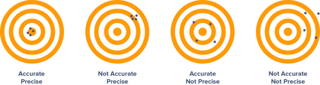
Exactly how precise do you need to be? That’s defined by tolerance, and tolerance is defined by you. How much wiggle room do you have in your application? What’s an acceptable variance in the closeness to the measurement that precision is hitting? That will depend on your project, for example, a component with a dynamic mechanical assembly will require tighter tolerances than something like a simple plastic enclosure. If you’re defining a tolerance, you’ll likely want accuracy too, so let’s assume we’re measuring precision of shooting at the bullseye. Earlier, we defined the shots on the target pictured on the right as not precise.

However, if your tolerance range is fairly wide, it may be okay. The shots aren’t as close to each other as in the target on the left, but if the acceptable range of precision is the distance of ±2.5 rings, then you’re within spec.
How to Understand Accuracy and Precision in 3D Printing
There are a variety of factors to consider when thinking about accuracy and precision in 3D printing, but it’s also important to identify your specific needs. For example, a precise-but-inaccurate printer may be the best choice for some applications. A low-cost fused deposition modeling (FDM) machine will produce less accurate parts, but for a quick and dirty proof of concept model for an engineering meeting, it may not be important for the model to exactly match the CAD design. On the other end of the spectrum, if you are running low volume production on an HP Multi jet fusion 3D Printer, the parts must be accurate and precise so they function consistently from part to part with out fit up issues at final assembly.
The following reports are intended to give you real world examples of 3D printed parts and how closely we were able to print them to there original CAD designs. As we have more projects to share, our goal is to continue adding content to this page.
HP Multi Jet Fusion (MJF) 3D Printed part accuracy:
Approximate Part Accuracy*: +/- .010″ for the first 1 inch, +/- .005″ per inch thereafter
HP Multi Jet Fusion (MJF) produces parts with good accuracy and can print designs with complex geometry. The MJF printer lays down a layer of material, then sprays fusing agent on the areas that need to be melted on that layer and detailing agent around the perimeter of the areas that have been coated with fusing agent to allow for fine details to be produced. Due to the high heat used to melt / fuse the part material warping and non uniform part shrinking can occur if the build chamber is cooled too rapidly. To restrict the likelihood of parts warping or shrinking after being printed MJF 3D printers are coupled with a standalone build unit cooling station. This system is used slowly cool the parts after they are built in the MJF 3D printer (generally for 50% of the time that the build took).
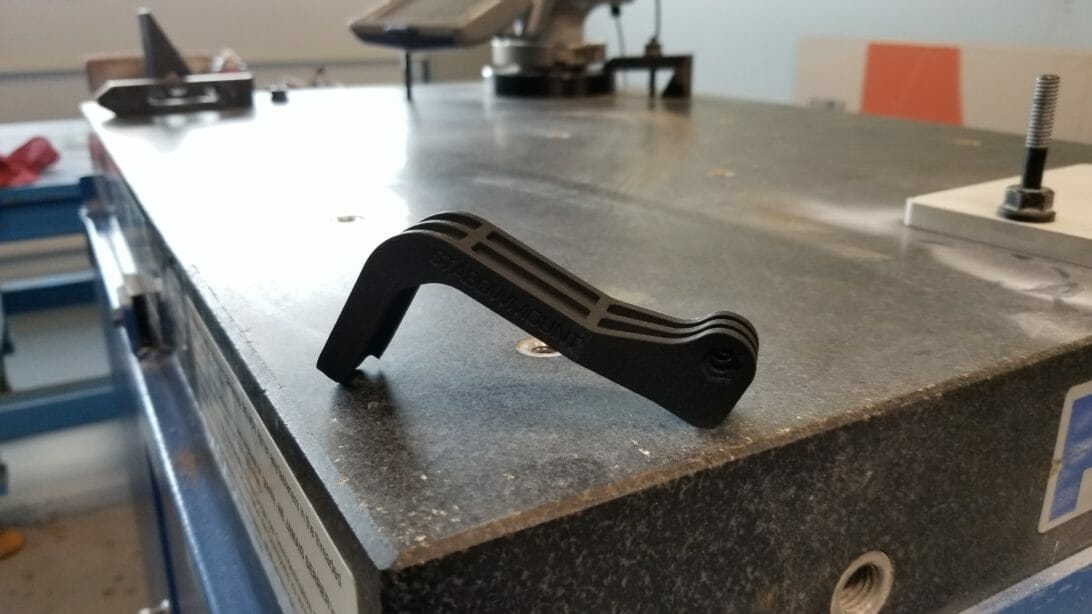
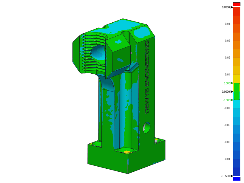
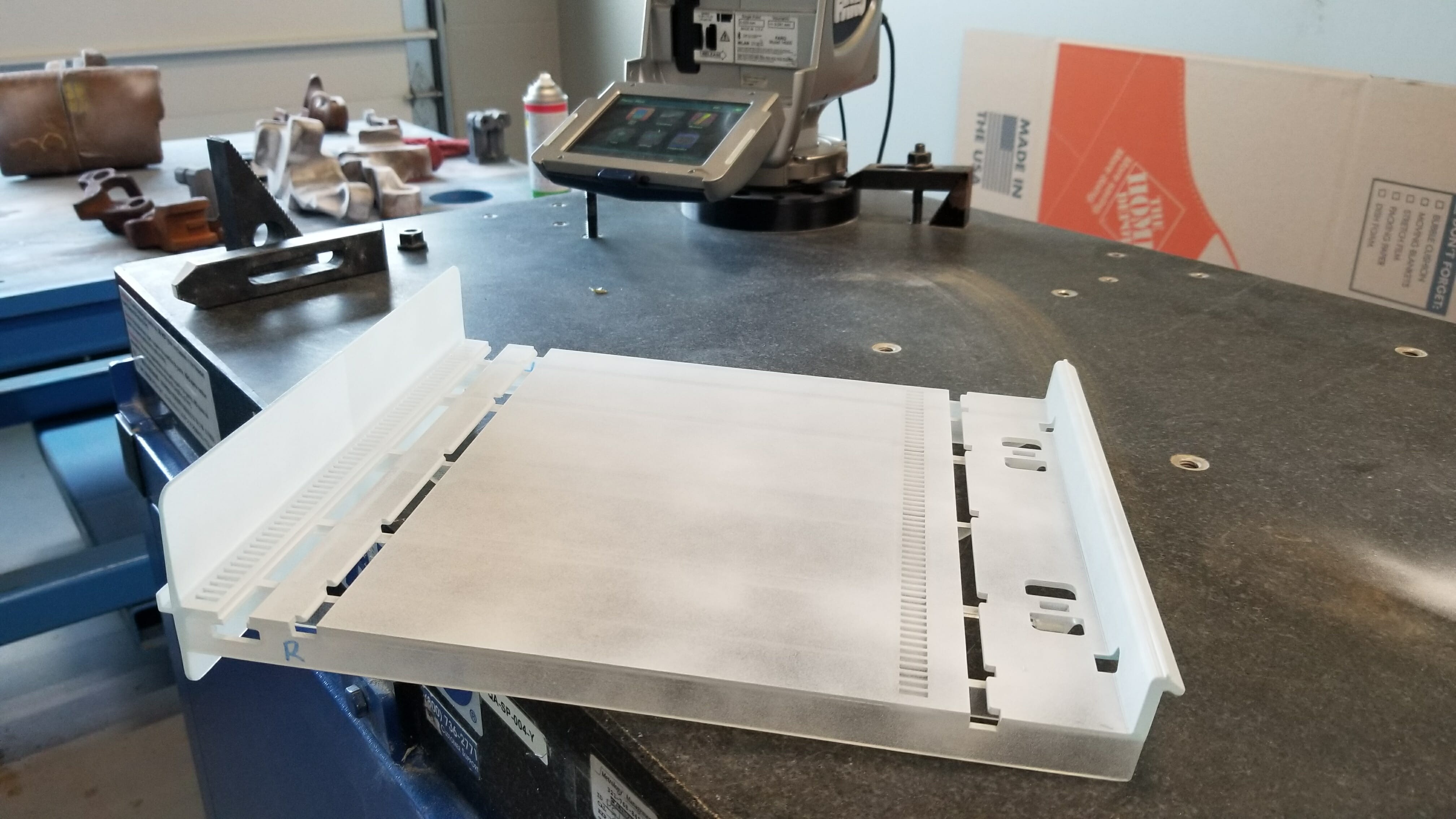
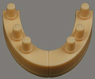
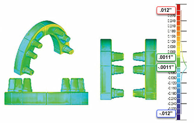
Stabowmount 3D Printed part accuracy:
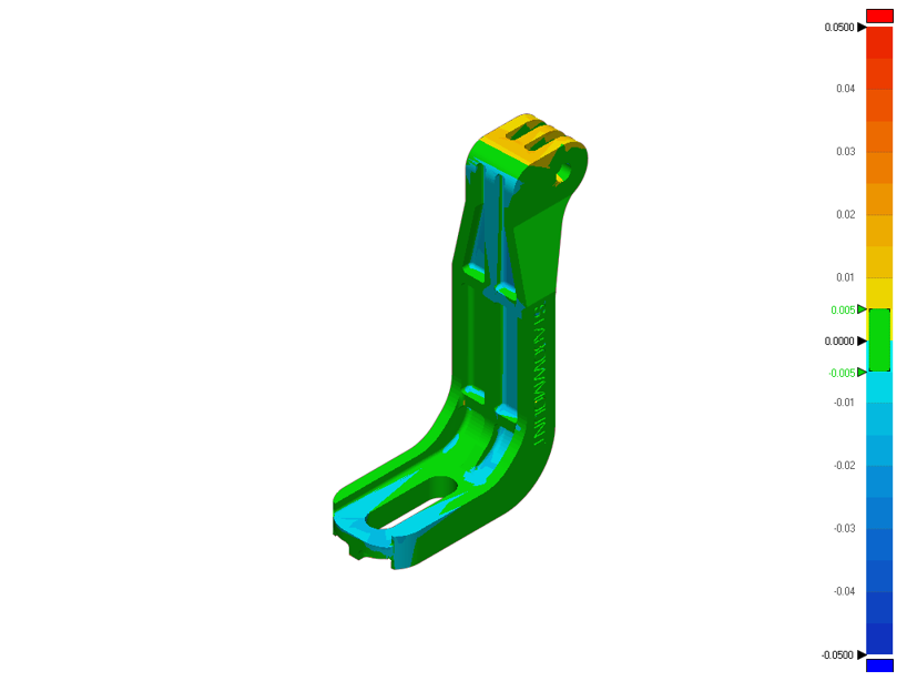
Full 3D Printed part accuracy inspection report
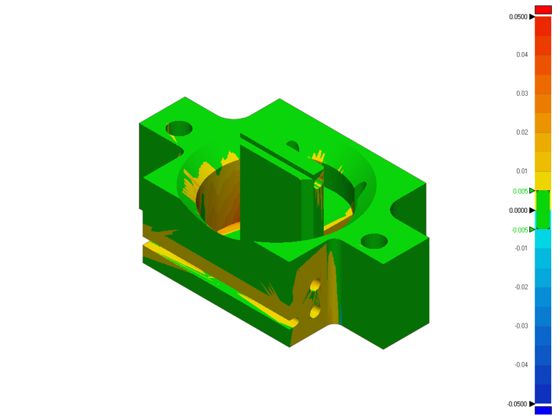
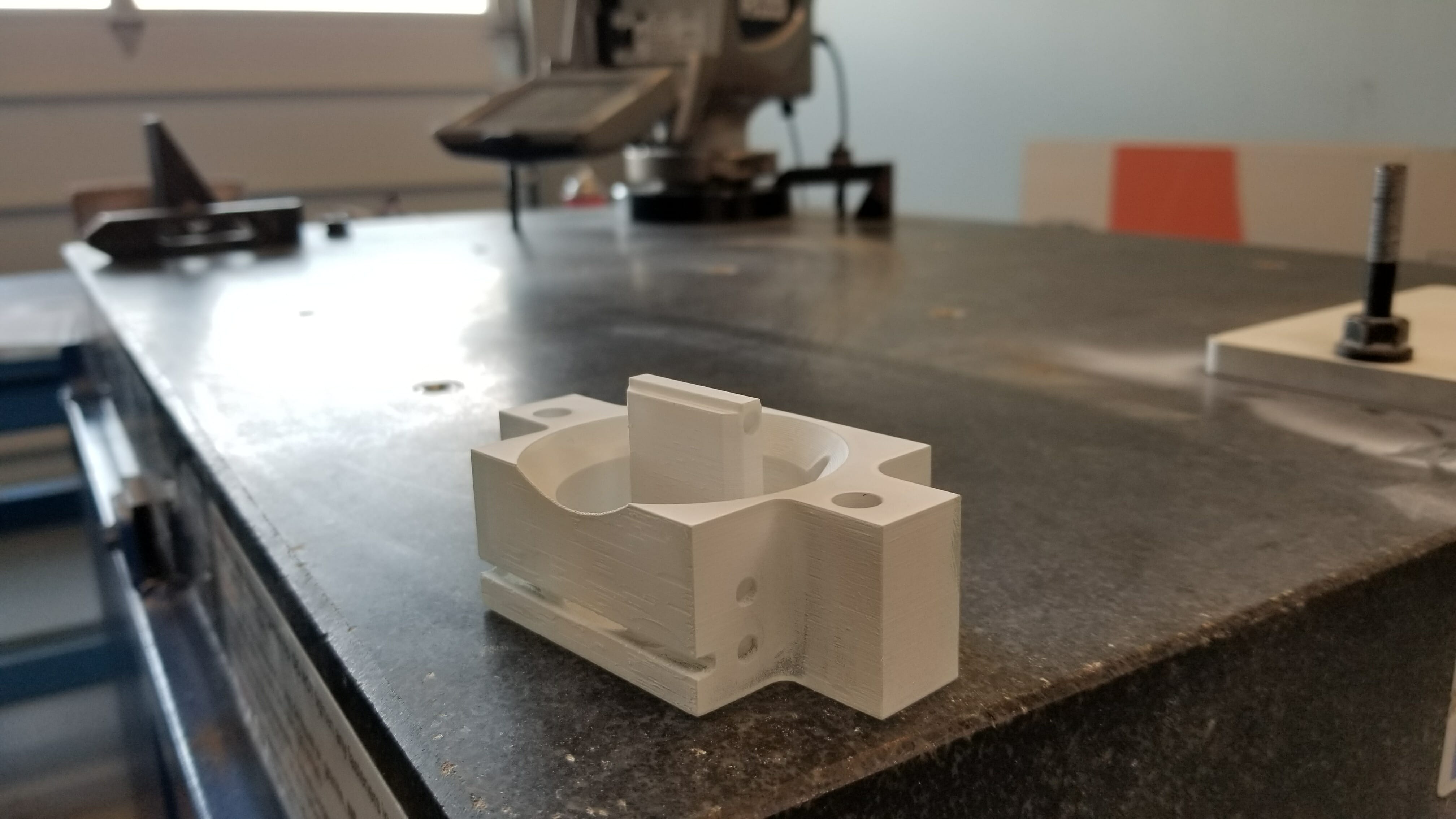
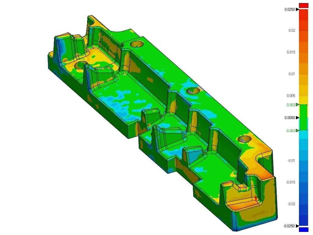
Replacement Part for industrial equipment 3D Printed part accuracy:
Full 3D Printed part accuracy inspection report

Stereolithography (SLA) 3D Printed part accuracy:
Approximate Part Accuracy*: +/- .025″ for the first 5 inches, +/- .0025″ per inch thereafter
SLA (stereolithography) printers use a laser to UV cure specific areas of a resin tank to form a solid part one cross section at a time. These cured areas however are not at full strength until post processing with UV. Because of this and the angle and orientations that SLA parts are typically printed at, sagging of unsupported spans can occur.
As one layer is built up at a time, this effect becomes cumulative leading to the dimensional discrepancies sometimes seen in tall SLA parts. Dimensional discrepancies can also occur because of the peeling process used by some SLA printers. The pulling force during the peel process can cause the soft print to bend which again can accumulate as each layer is built up.
Resins that have higher flexural properties (less stiff) are at a greater risk of warping and may not be suitable for high accuracy applications.
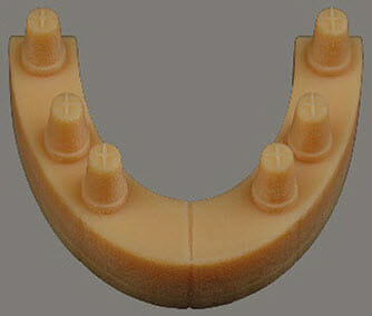
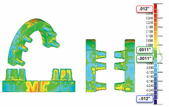
Prototype nest 3D Printed part accuracy:
Full 3D Printed part accuracy inspection report
Prototype Tray 3D Printed part accuracy:
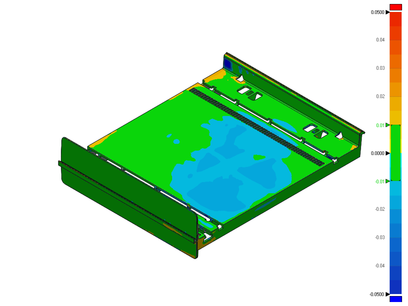
Full 3D Printed part accuracy inspection report
Prototype nest 3D Printed part accuracy:
 Full 3D Printed part accuracy inspection report
PolyJet 3D Printed part accuracy:
Approximate Part Accuracy*: +/- .005″ for first 1 inch, +/- .0025″ inch per inch thereafter
PolyJet is a very accurate form of 3D printing because there is no heat involved in the printing process warping and shrinkage rarely occur.
Most dimensional accuracy issues relate to features and thin walls that are printed below printer specifications. Material jetting prints support as a solid structure from a soft secondary material that is removed after printing. The solid nature of the support results in surfaces in contact with the support being printed to a high level of accuracy. Care must be taken when handling parts produced via material jetting as they can warp and dimensionally change as a result of exposure to ambient heat, humidity, or sunlight.
FDM 3D Printed part accuracy:
Approximate Part Accuracy*: +/- .035″ for the first 5 inches, +/- .010″ per inch thereafter
Fused deposition modeling (FDM) is best suited for low-cost prototyping, where form and fit are more important than function. FDM produces parts one layer at a time by extruding a thermoplastic onto a build plate.
For large parts, this can lead to big variations in temperature across the build platform. As different areas of the part cool at different rates internal stress cause the print to move leading to warping or shrinkage. Solutions like printing rafts, heated beds and radii at sharp edges and corners can help to reduce this. Different materials are more prone to warping than others. For example, ABS is know to be more susceptible to warping than PLA.
SLS 3D Printed part accuracy:
Approximate Part Accuracy*: +/- .015″ for the first 1 inch, +/- .010″ per inch thereafter
Selective Laser Sintering (SLS) produces parts with high accuracy and can print designs with complex geometry. A laser selectively sinters powder one layer at a time to for a solid part.
To restrict the likelihood of parts warping or shrinking during printing, SLS printers use heated build chambers that heat up the powder to just below the sintering temperature. This does still however result in temperature gradients in large SLS parts where the bottom of the part has cooled while the recently printed top layers remains at an elevated temperature. To further mitigate the likelihood of warping occurring parts are left in the powder to cool slowly (often for 50% of the the total build time).
CLIP / DLP 3D Printed part accuracy:
Approximate Part Accuracy*: +/- .005″ for the first 1 inch, +/- .0025″ per inch thereafter
DLP is considered to be one of the most accurate 3D printing technologies.
*A note on printed part accuracy: The accuracy of a part manufactured on a 3D Printer can be extremely dependent based on the size and overall design of a part. For projects that require tight accuracy we recommend reaching out directly to our sales engineers who will review your parts and offer a realistic estimate of their potential printed accuracy based on their design. They can also offer design advice and post processing options to help improve the accuracy of your part.