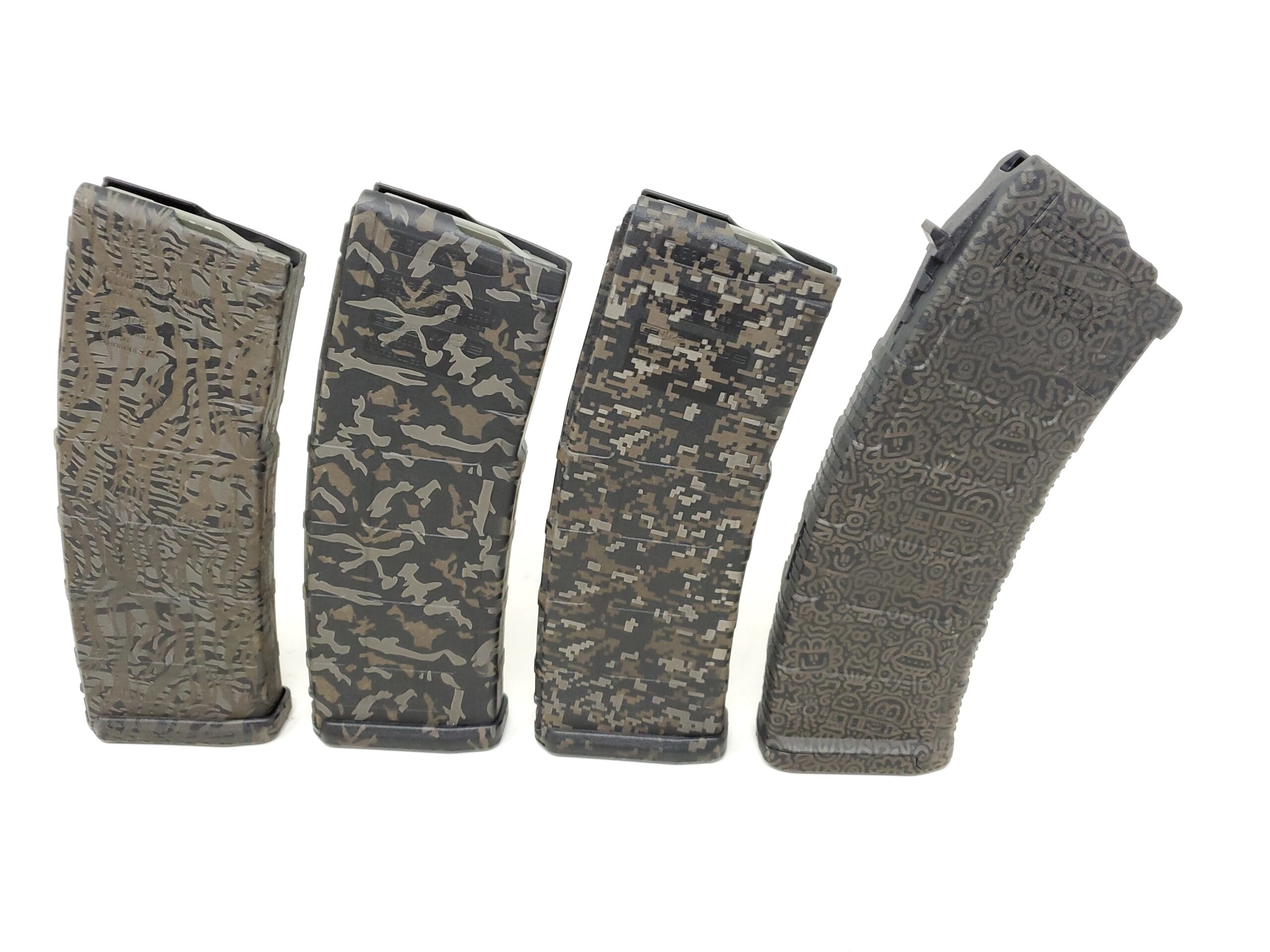
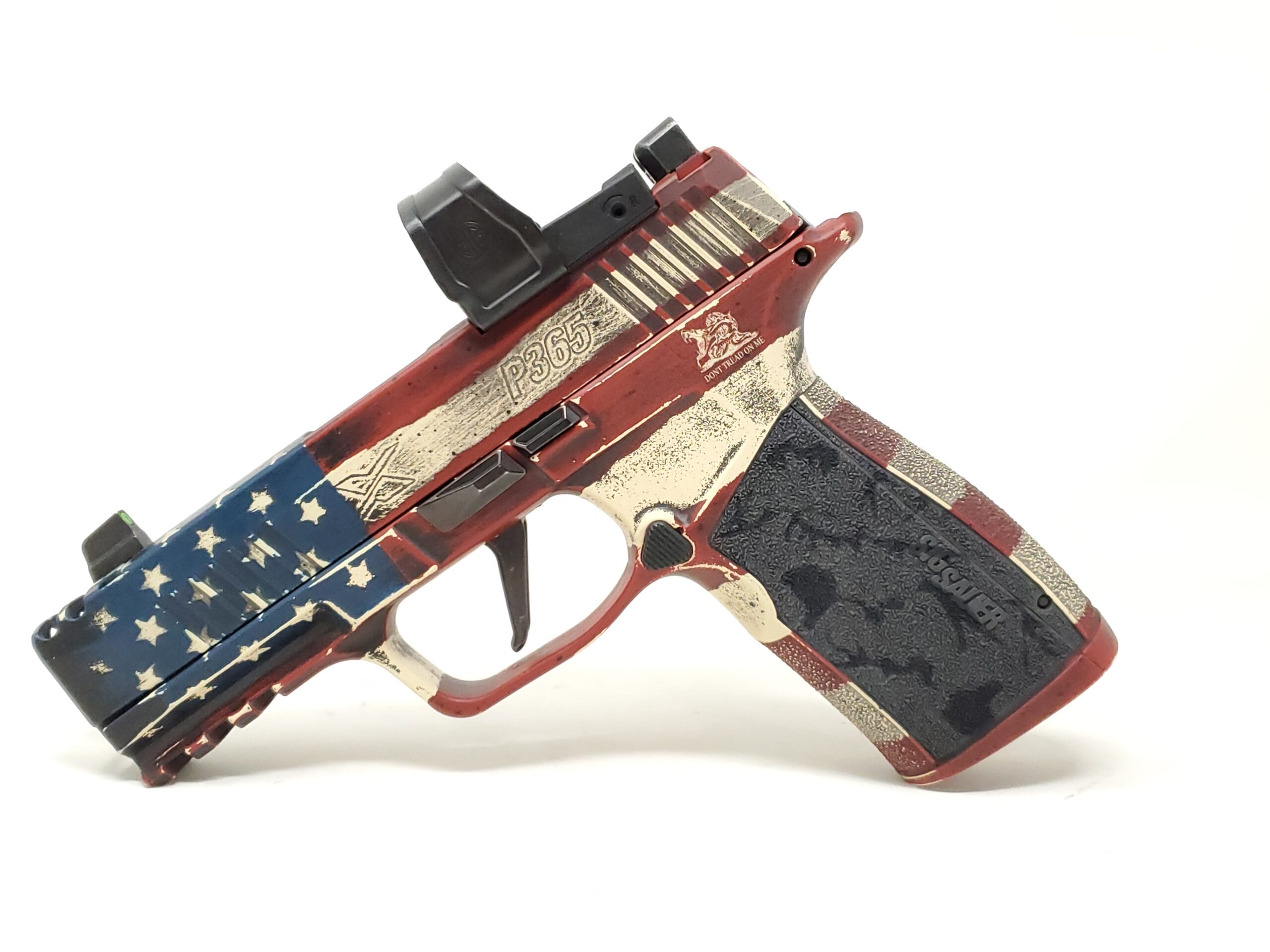
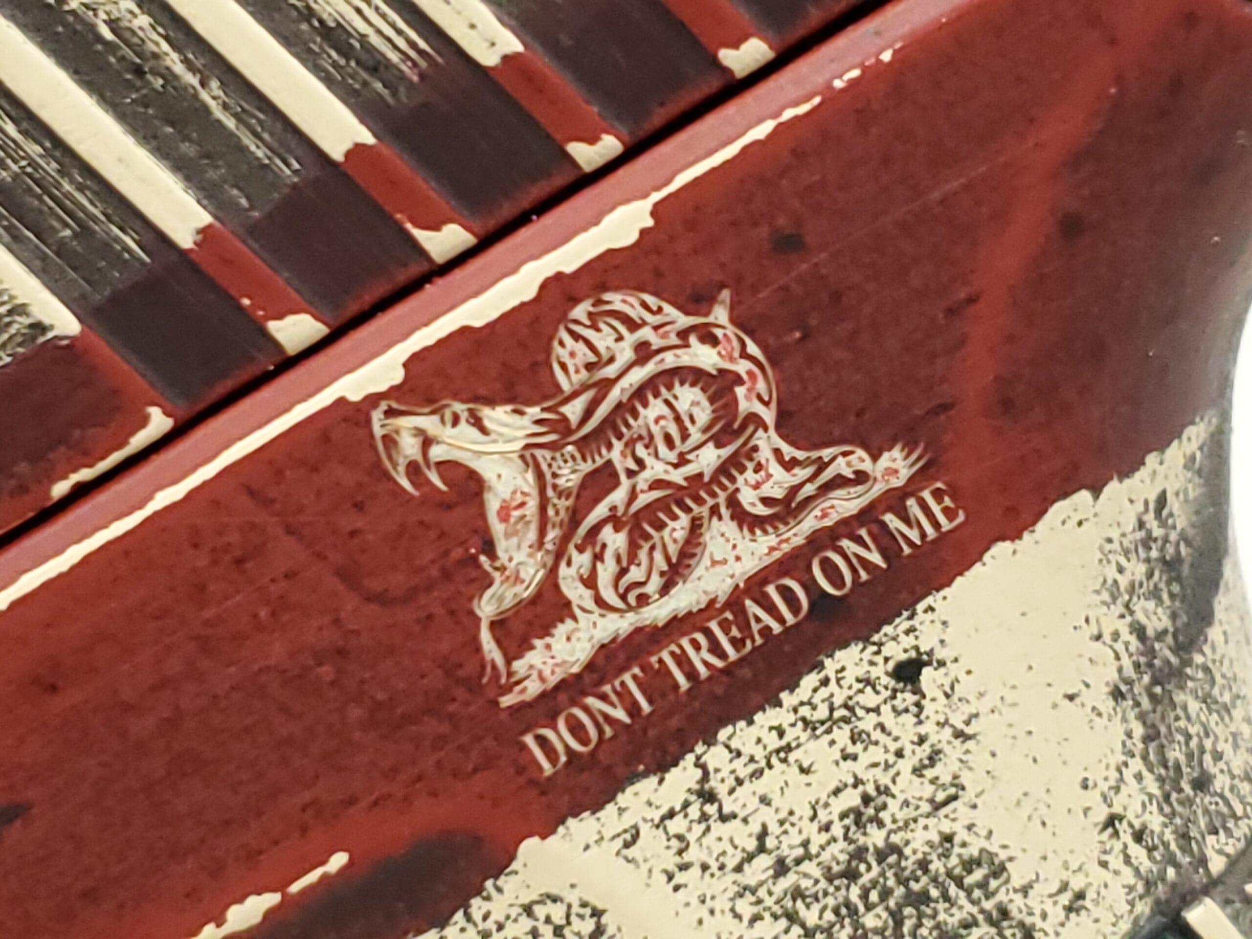
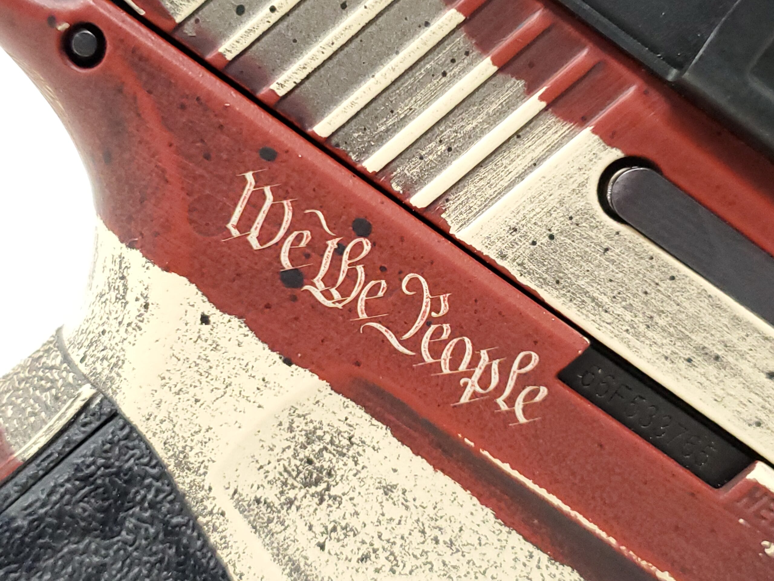
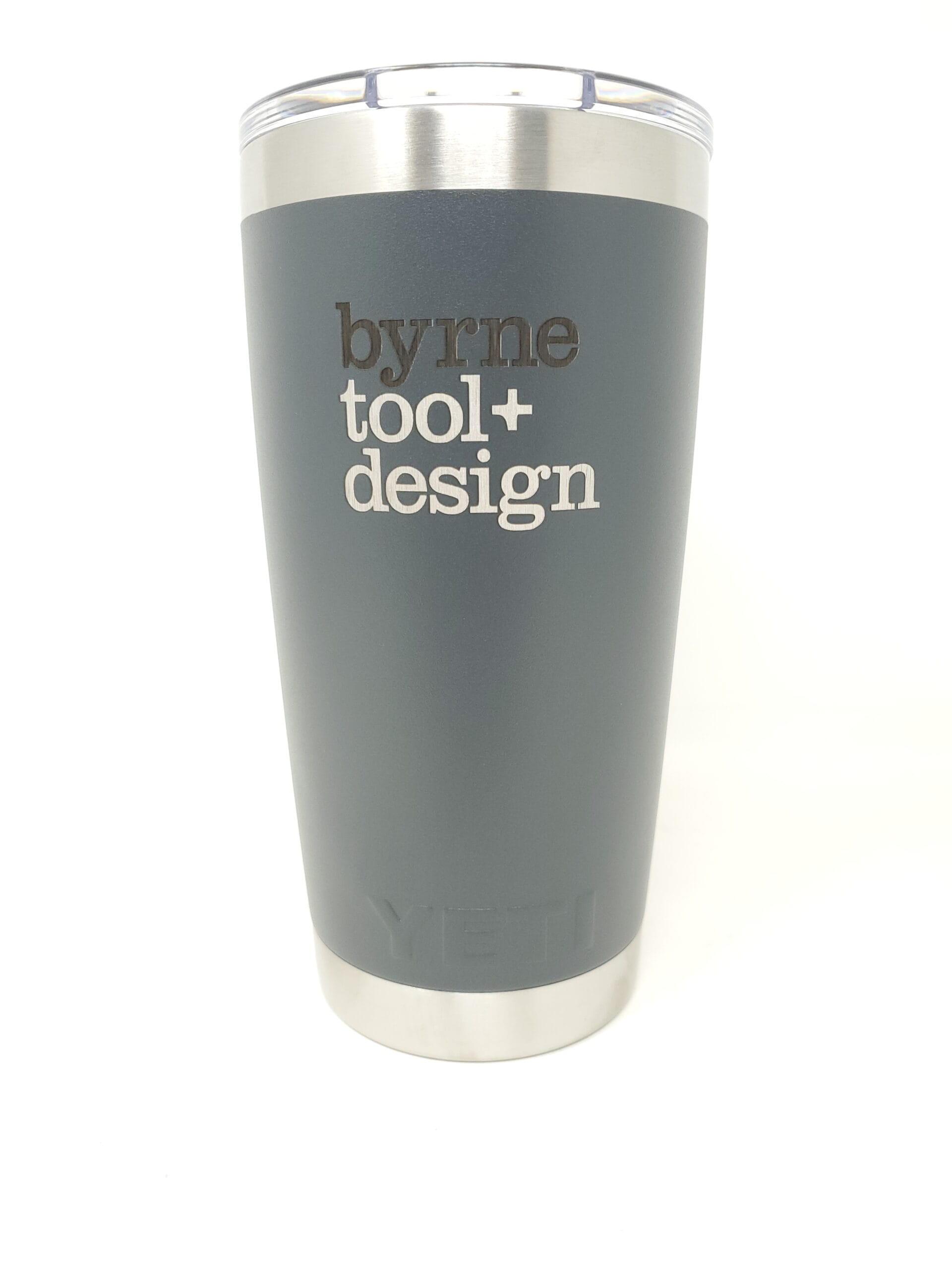
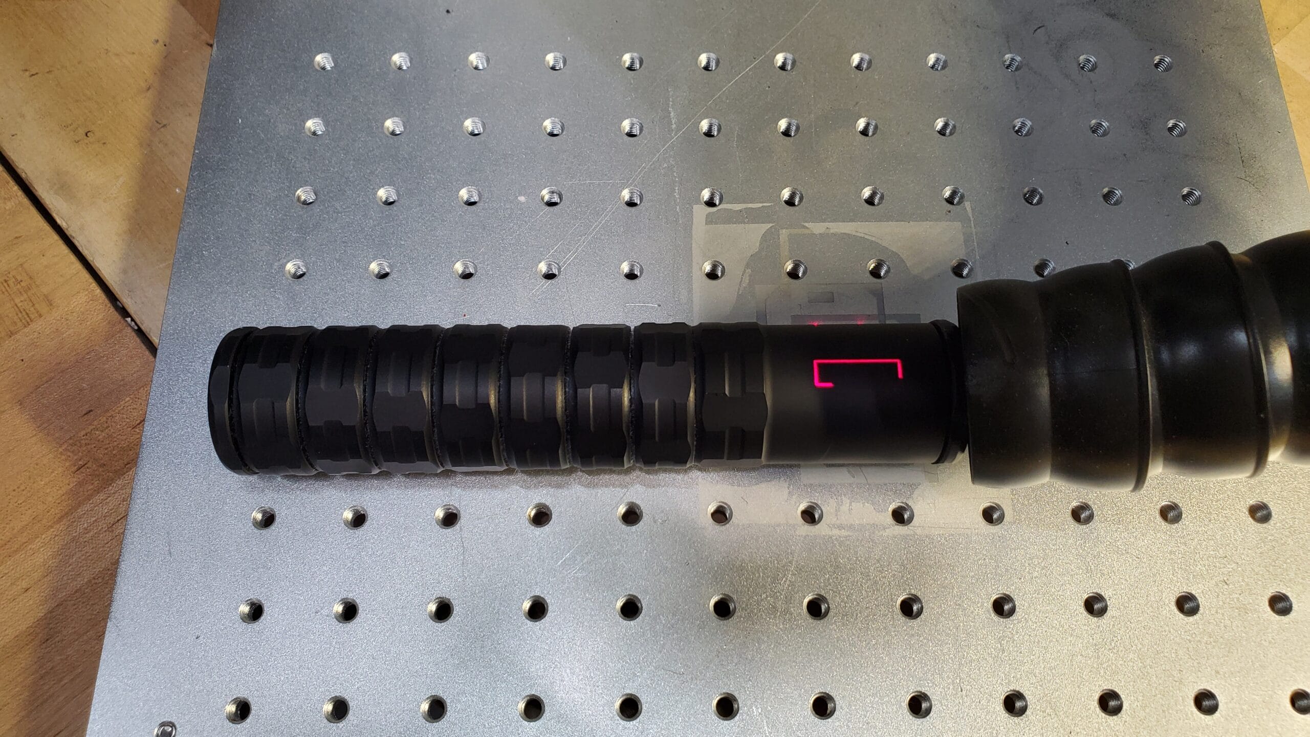
Deep Laser Engraving is a process by which a beam of focused light interacts with the surface material to vaporize or remove many layers leaving a cavity in the surface that is noticeable to the eye and touch. The amount of material removed and the depth of the cavity can be controlled by a skilled engineer to produce quality engravings in any material type. This includes 3D printed parts in material’s like ABS, Nylon 12, and some resins. Depending on the type of 3D Printing technology being used and the orientation of the part during printing it can sometimes be difficult if not impossible to get text to turn out well on the part. This is where using deep laser engraving to add in the text or logos after printing can be extremally useful. Deep laser engraving can also be combined with Cerakote to enable multi color logos by lasering off the top Cerakote color to reveal a different Cerakote color underneath it.
Deep Laser Engraving vs. Laser Engraving or Etching
The difference between deep laser engraving and laser engraving/etching is a matter of depth and where the line falls is subjective based on the shop you are dealing with and the material to be engraved. Going .005” deep on aluminum is very different that doing it on titanium and both are different than stainless or tool steel. An operator must have the skill, experience and most importantly the right laser for deep engraving on that material because most lasers generate heat. Excessive heat while deep engraving will damage and potentially destroy a part thus choosing the right laser engraving service provider is crucial.
Why Is Deep Laser Engraving Needed?
Forerunner 3D Printing can hit and hold depths in excess of .010” on flat or curved surfaces, inside radii and in locations unreachable by a CNC or other mechanical engraver.
Deep laser engraving is available on all material types, including stainless steel and titanium.
Deep Laser Engraving is an efficient and economical solution for injection mold cavities, inserts, core pins, dies and many other applications.
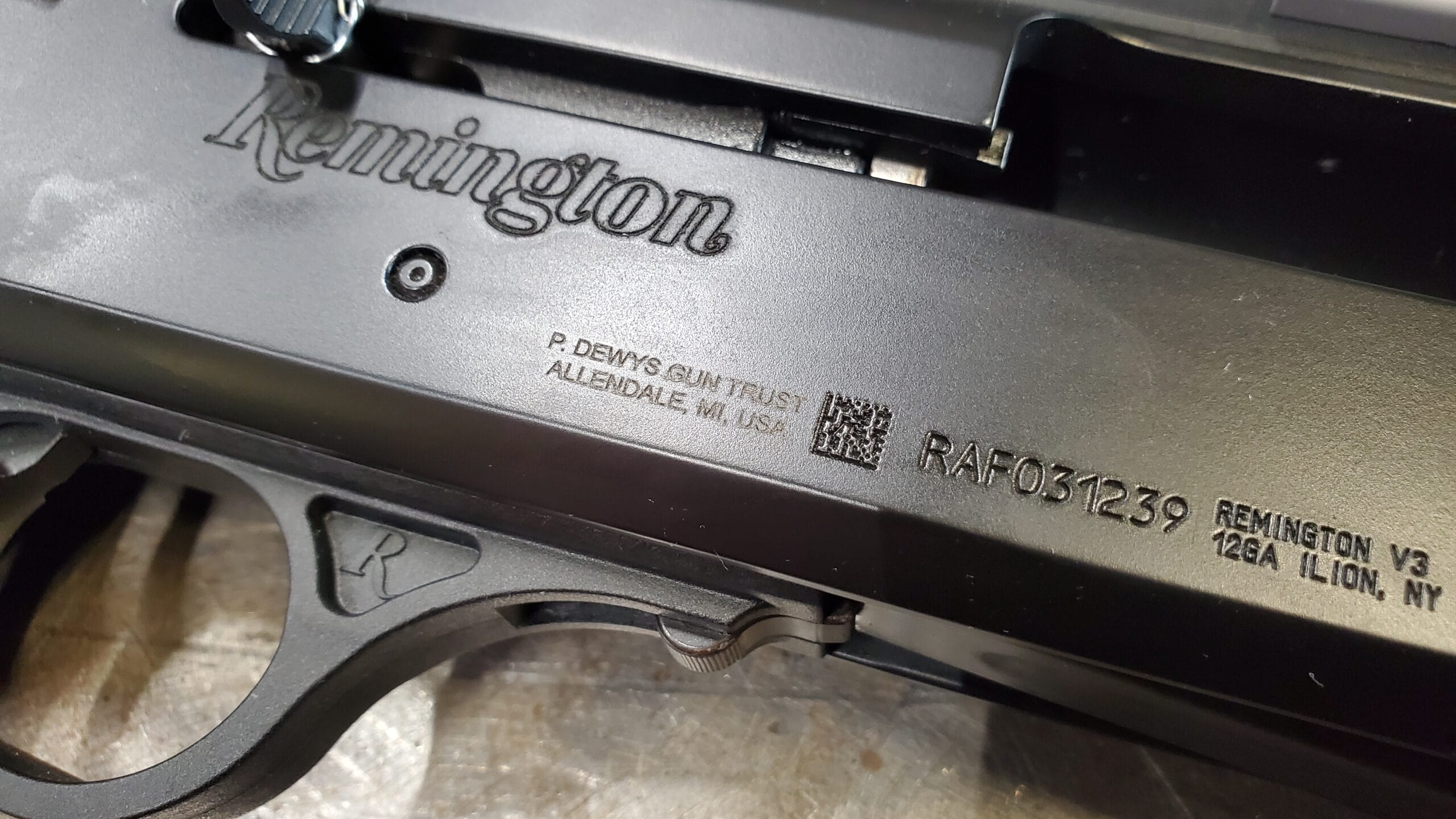
The laser can produce any type of mark ranging from simple text to complex logos, shapes, barcodes and 2D Data Matrix Codes. F3DP uses a high power laser with a spot size less than .003” that produces a superior mark on all metal types.
Laser engraving is permanent, able to withstand the harshest environments.
The process is computer driven and controlled making it fast and accurate every time.
Firearms Deep Engraving Services
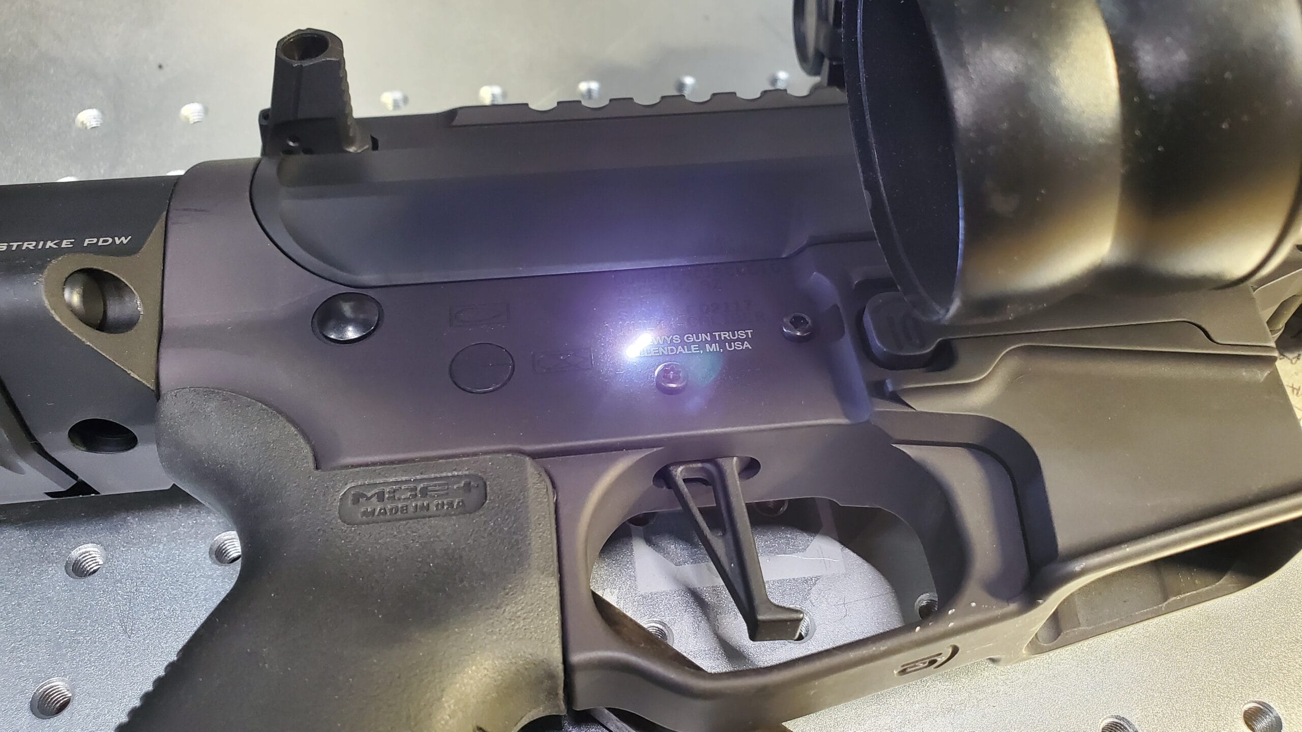
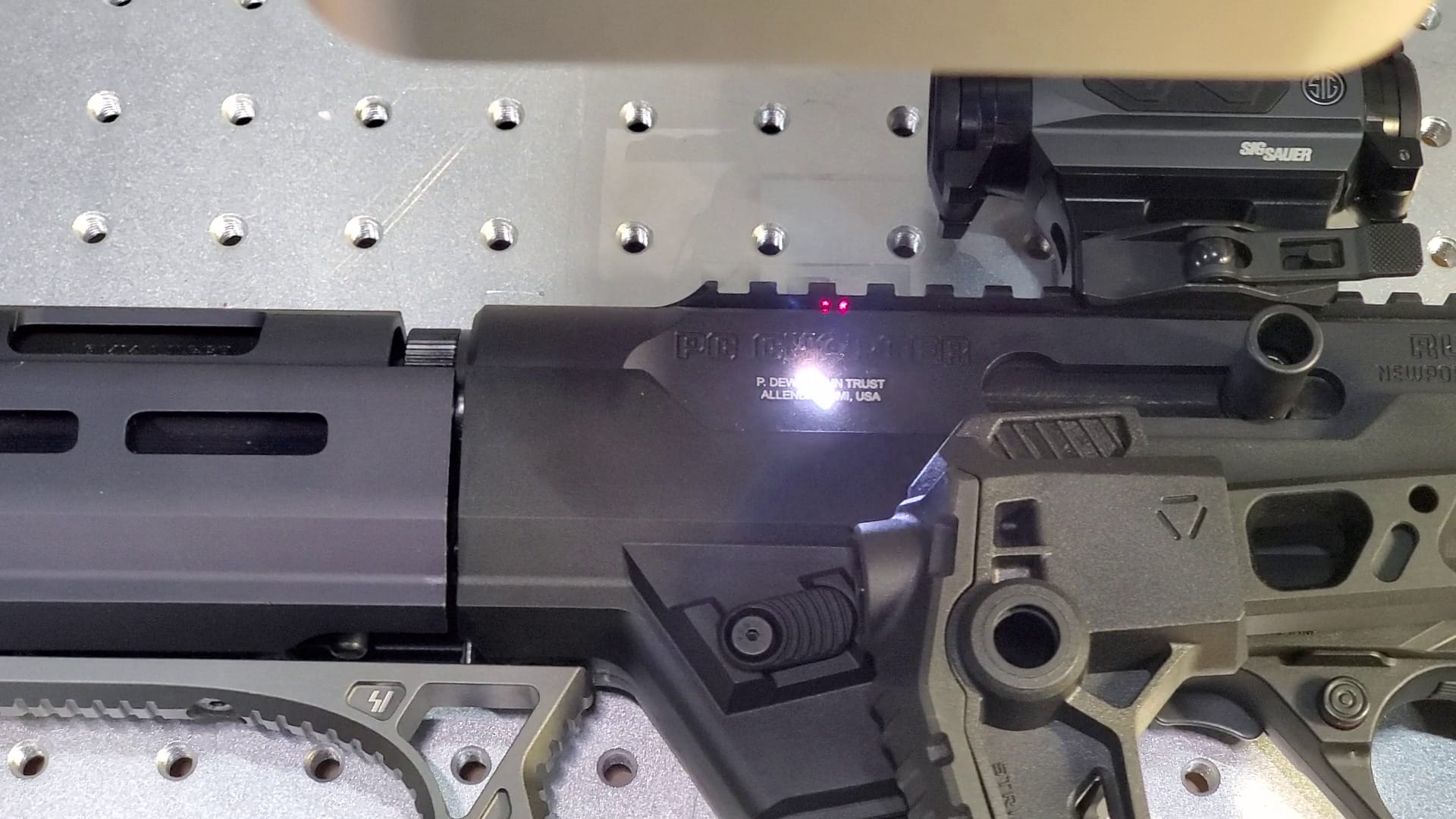
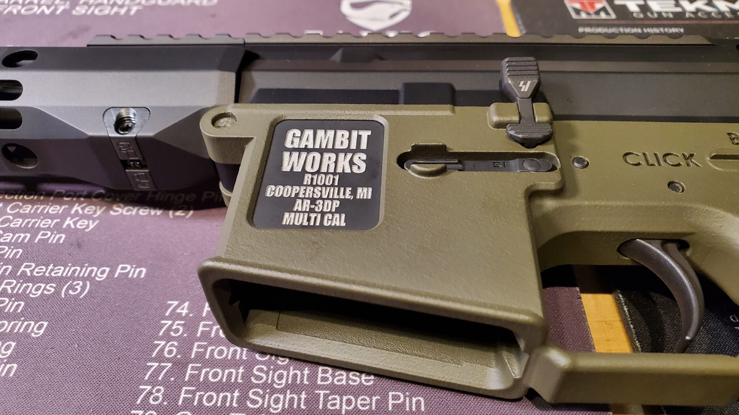
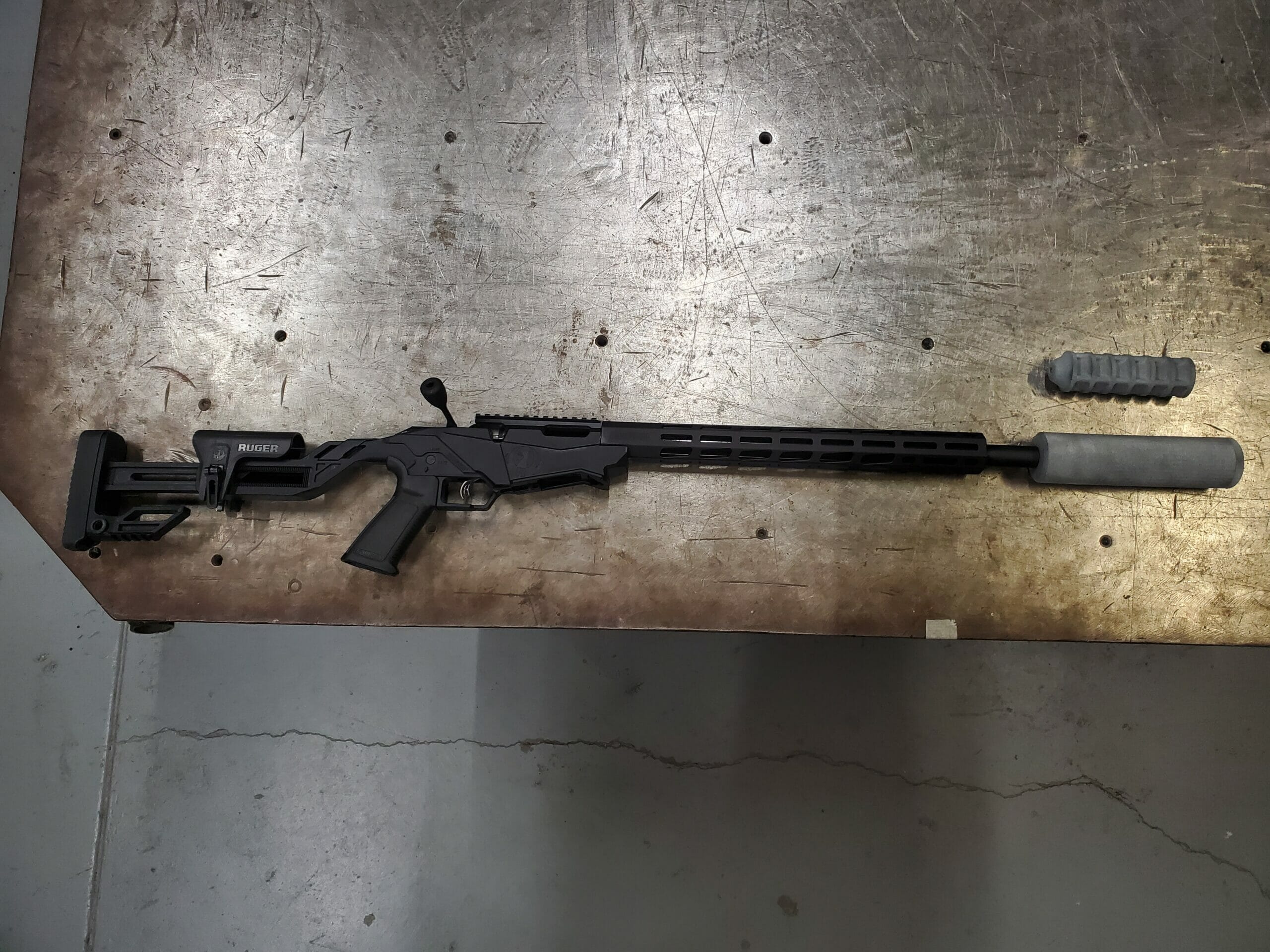
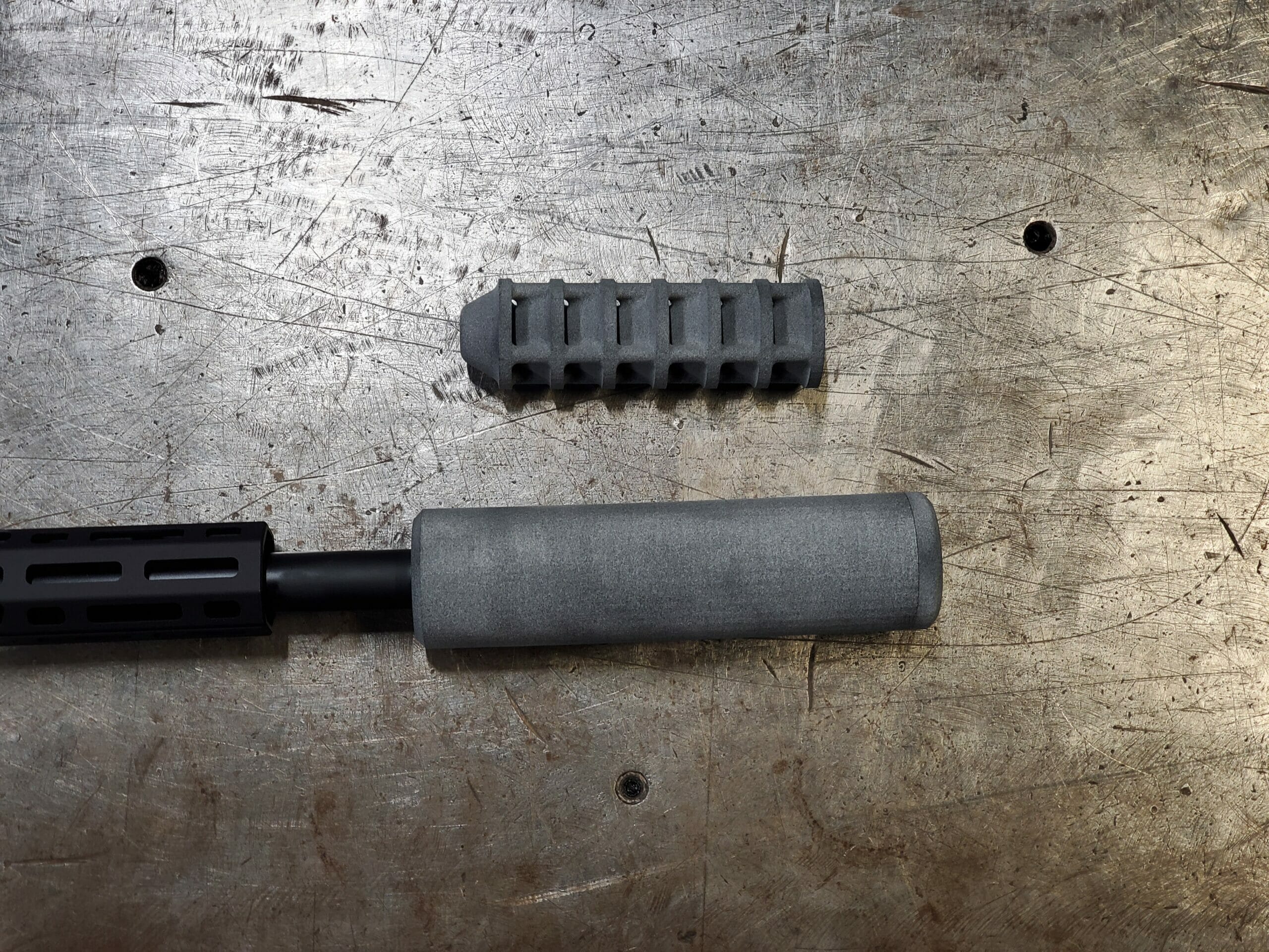
F3DP has an FFL07 / SOT02 for Firearms Manufacturing, which provides us the capability to receive, transfer and process assembled NFA Firearms including SBR and Suppressors. Typical engraving work for NFA Firearms includes Trust Engraving, logos and other operating marks.
When a person registers a Short Barreled Firearm or builds their own Firearm Suppressor they are required by the ATF to engrave their personal or Firearms Trust information upon it permanently, deep engraving is very well suited for taking care of this task. We do offer this as a service to customers.
Cost: $75 for the first firearm
If you have multiple items that all need to be engraved with the same information (for example Trust information) then each additional item will cost $25.
We allow for you to either drop off your item for marking or you can wait in our parking lot while we do the marking so you can take it home with you immediately.
WE DO NOT ALLOW WALK-INS, you must schedule an appointment to drop off your item for marking.
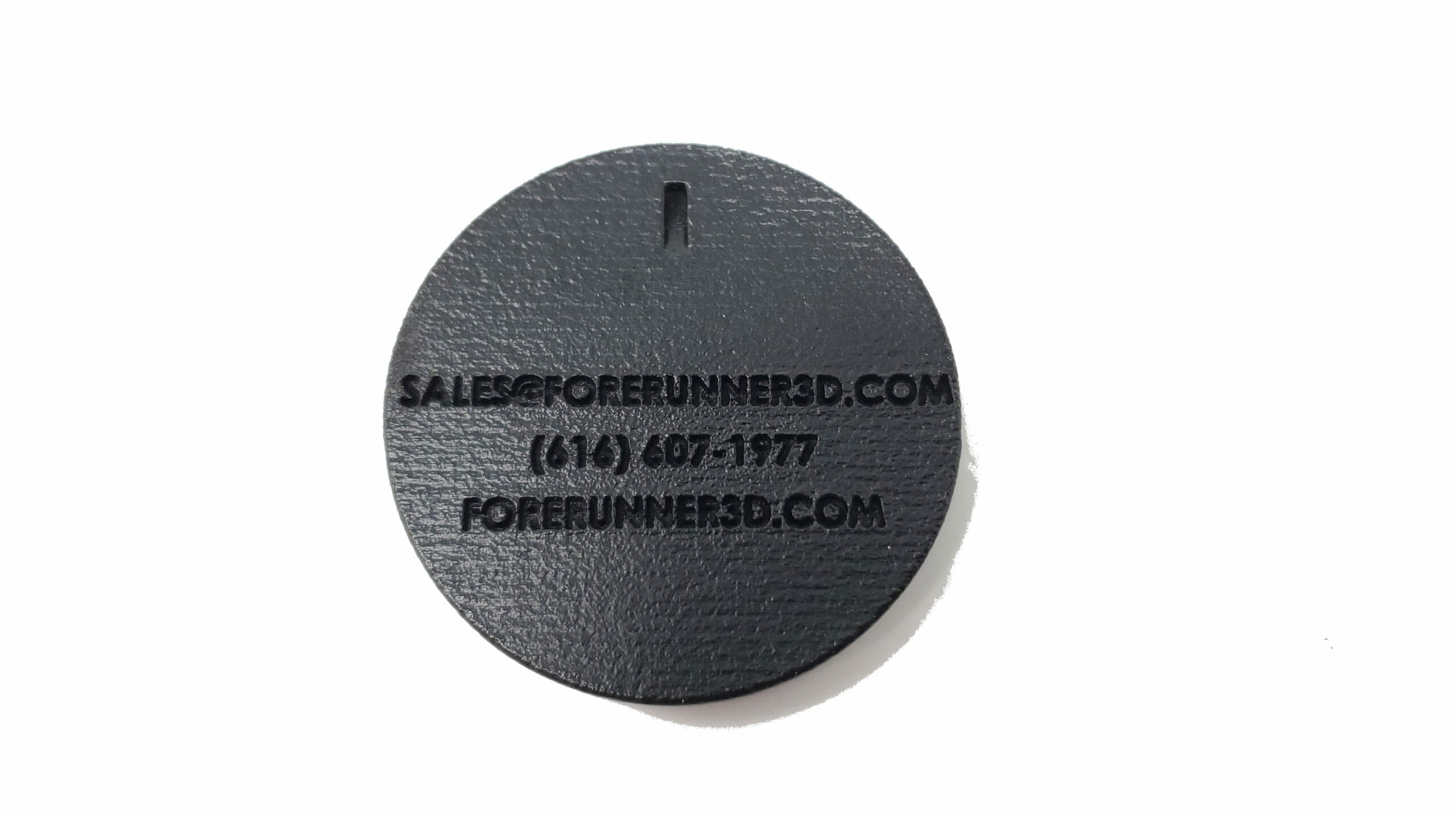
For any questions or to schedule an appointment for your project please contact us at: sales@cerakoteexpress.com
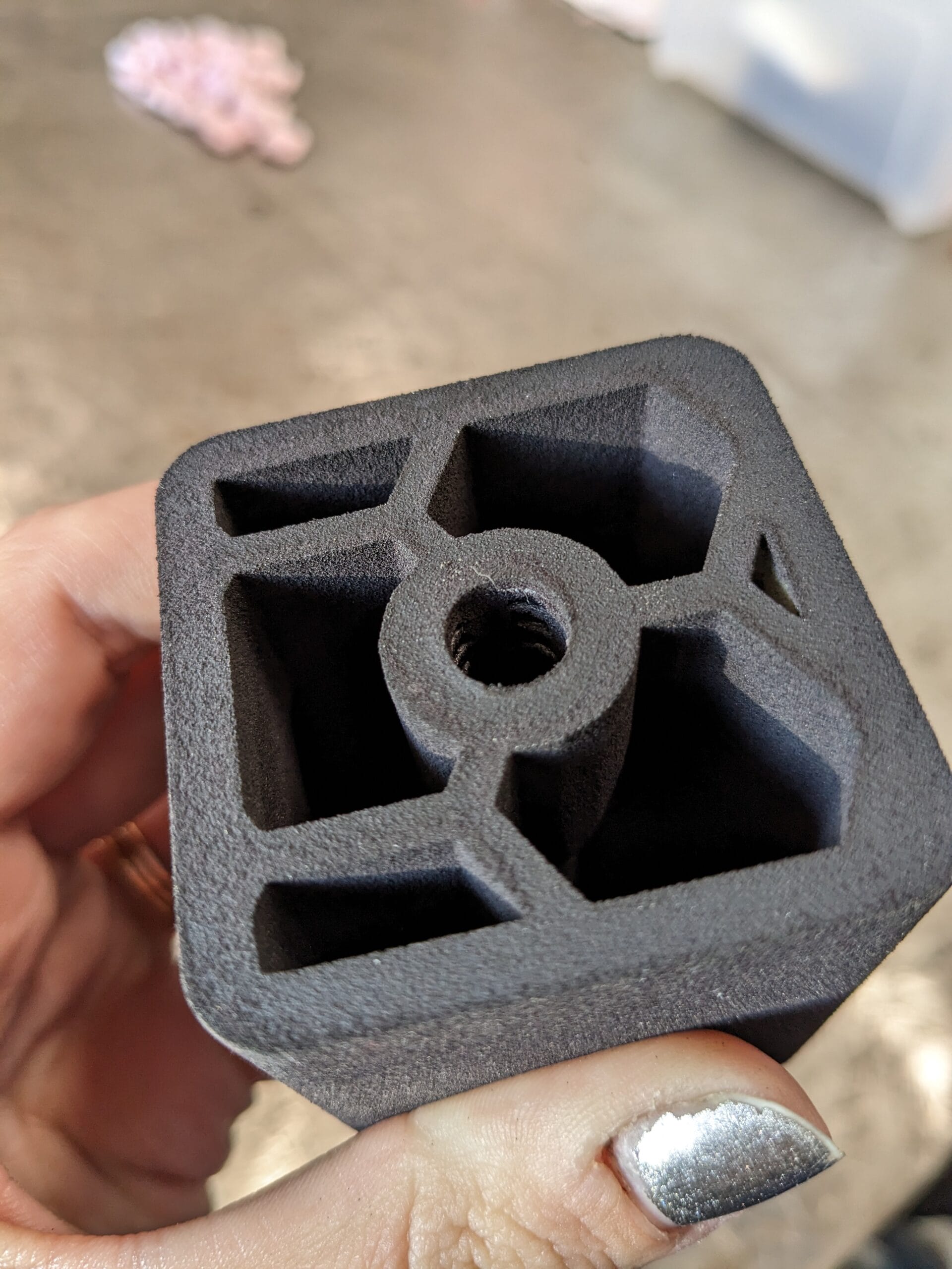
There are many different ways of adding threads to 3D printed parts, this guide specifically covers using E-Z Lok Inserts for MJFTPU Rubber parts. At Forerunner 3D Printing we run into assembly applications almost daily that require some type of thread when either designing our own parts or consulting on our customers designs. This can be challenging when using 3D Printed rubber parts as the only 2 viable options we have found is to either print the threads into the part directly or to install a metal E-Z Lok insert after the part is printed. The reason you may want to go with a E-Z Lok insert is if your part will be getting assembled and then taken back apart regularly which over time could wear out a printed in rubber thread. We have developed our own design guidelines for the holes these inserts are installed in. We recommend using our hole sizes to prevent any splitting of the TPU part during installation while still allowing for a strong connection between the printed part and the E-Z Lok insert.
E-Z Lok Insert Hole Design Guidelines:
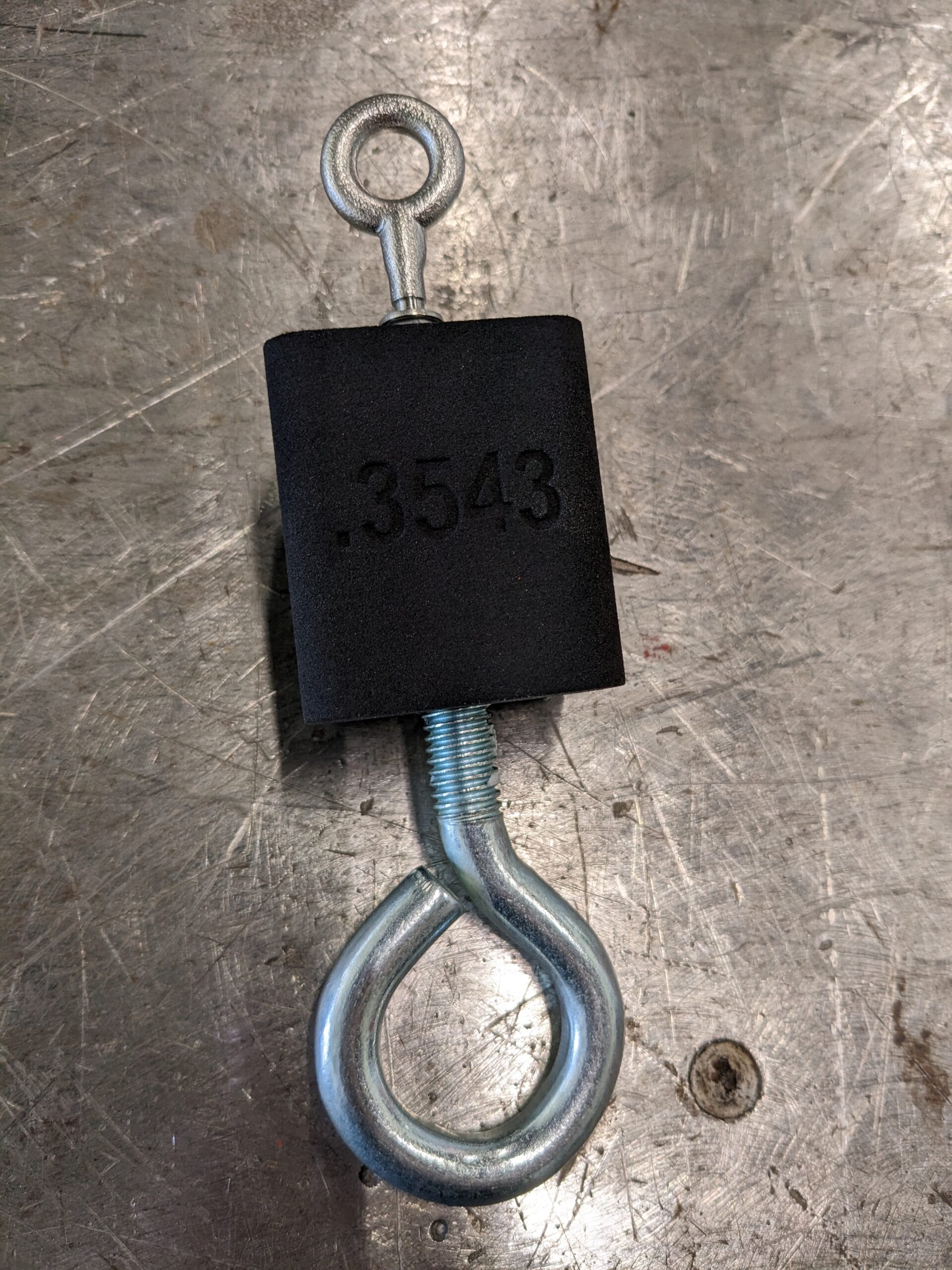
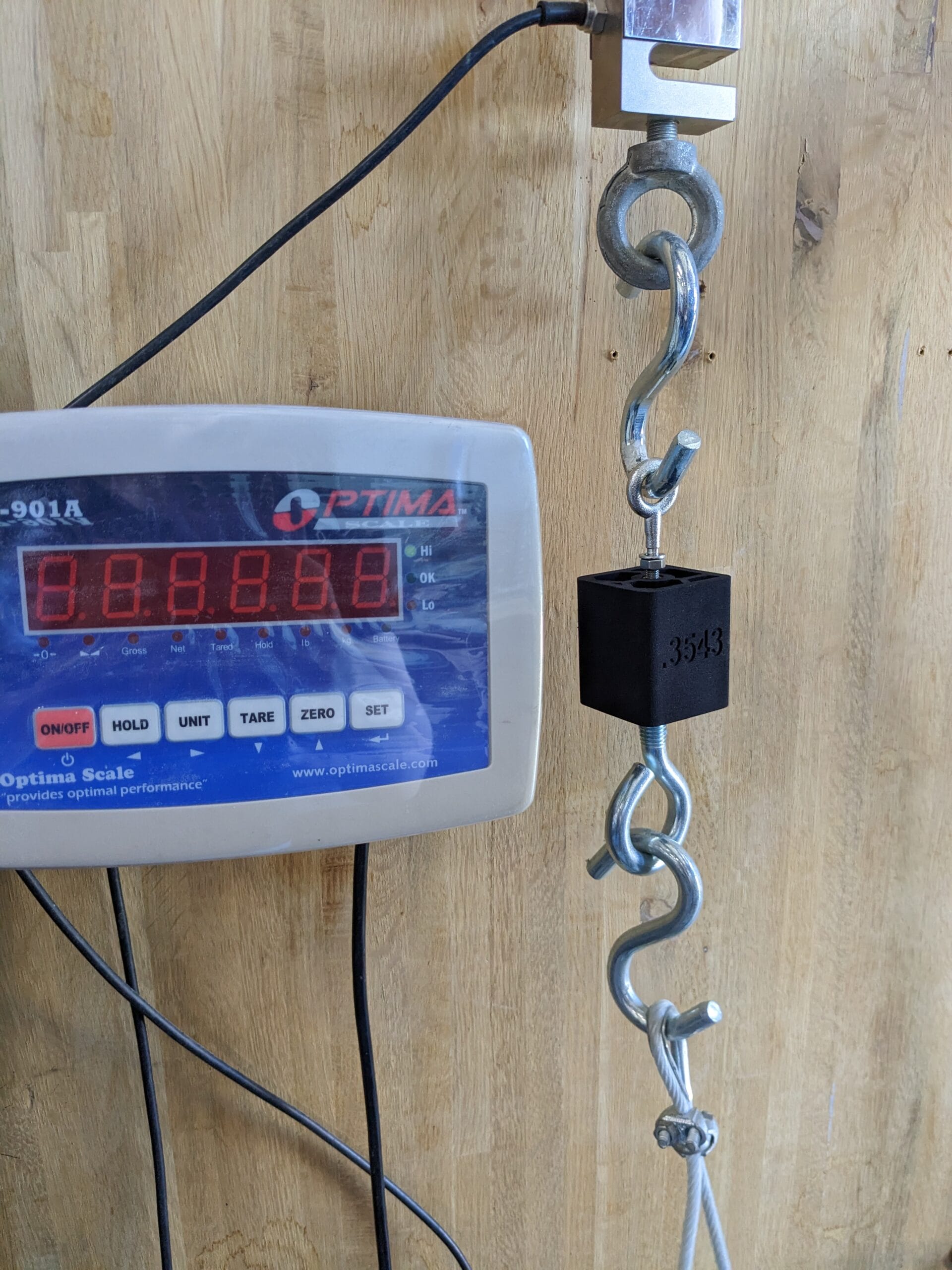
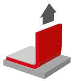
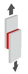
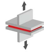
The video at the top of this page shows the testing used to establish the pull out forces in the chart below:
Comparison Between Printed In Threads & E-Z Lok Inserts:
Want a second set of eyes to check over your design or have a question? We offer free Design for Additive Manufacturing (DFAM) consulting for our customers:
Design guide for using dowel holes in 3D Printed Parts
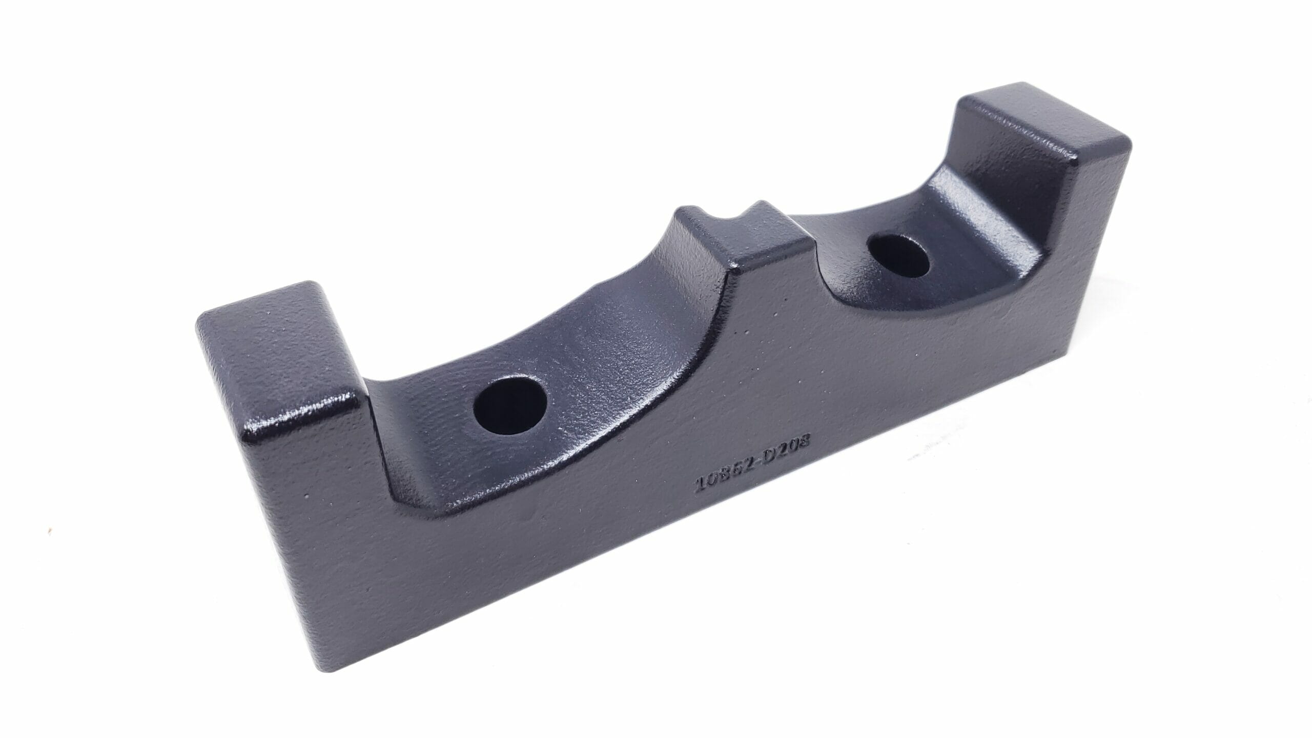
Dowel holes are commonly used to positively align two components together during assembly and then to help keep them aligned during use. They can also help to take heavy loads off of fasteners holding the assembled parts together. It is common for 2 dowel holes to be used per part, using more holes then this is not necessary and will generally over constrain the parts being assembled causing them to go together difficultly if at all. Typically dowel holes are made using precision machining equipment like Mills or Drill Presses and due to this can be placed in a desired location very accurately and also sized to be either a press fit or a slip fit.
When being used on parts that will be 3D Printed its important to understand that the printed parts will not have the same level of accuracy as that of parts that are machined (for more detailed on printed part accuracy please see our page on the topic). This means that it is important to understand how to design around this limitation and still get all the benefits of using dowels in your assembly. There are a few general rules of thumb that our inhouse engineering department has developed over the years that make using 3D Printed dowel holes easy and successful:
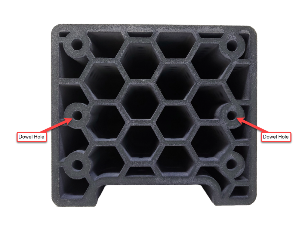
Rule #1: If your dowel holes will be CLOSER then 4″ to each other then you can use 2 true dowel holes, we recommend setting them to a press fit diameter as the printers USUALY print a bit big and if they end up to tight they can be opened up with a reamer to dial in a perfect fit.
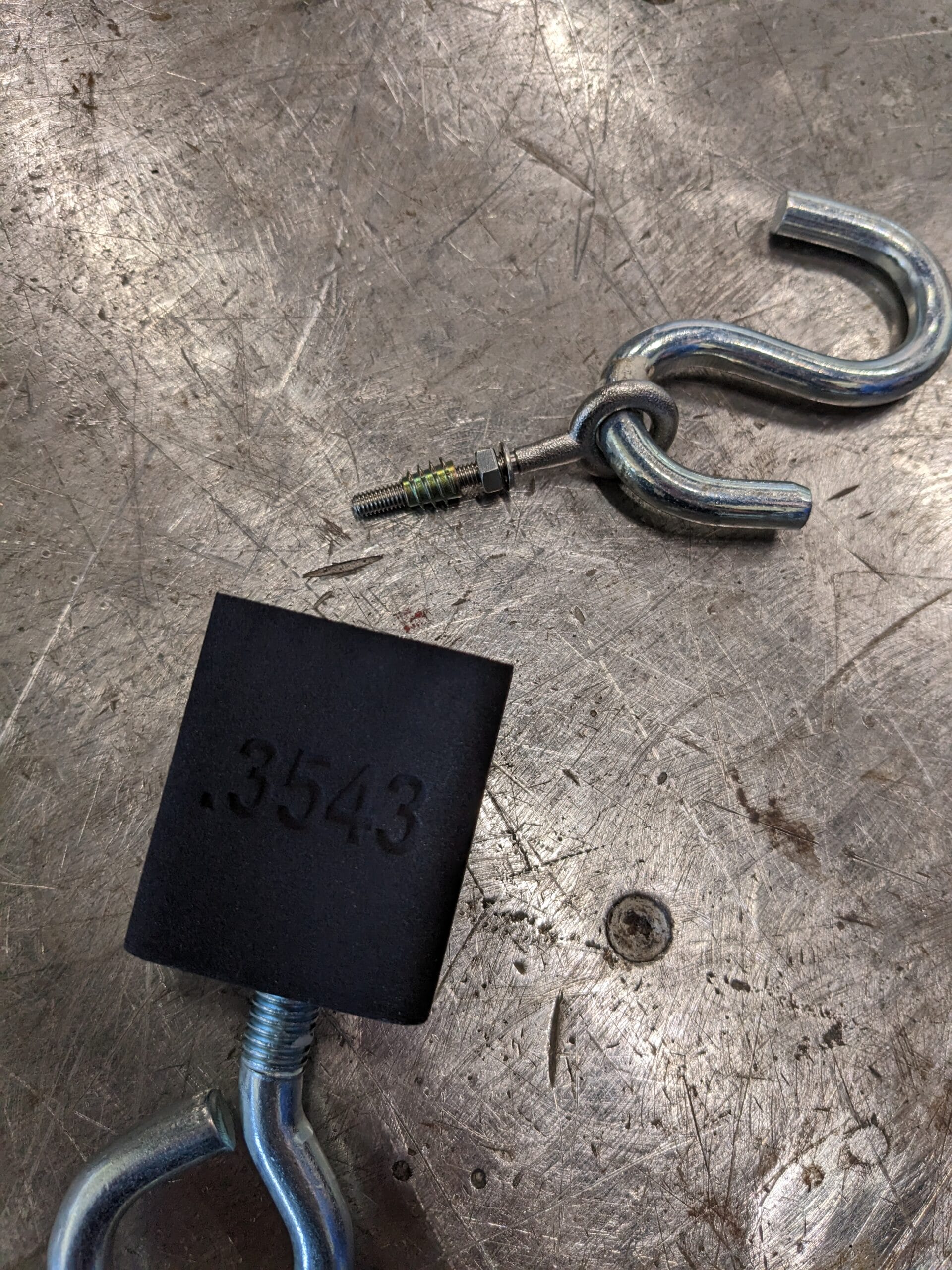
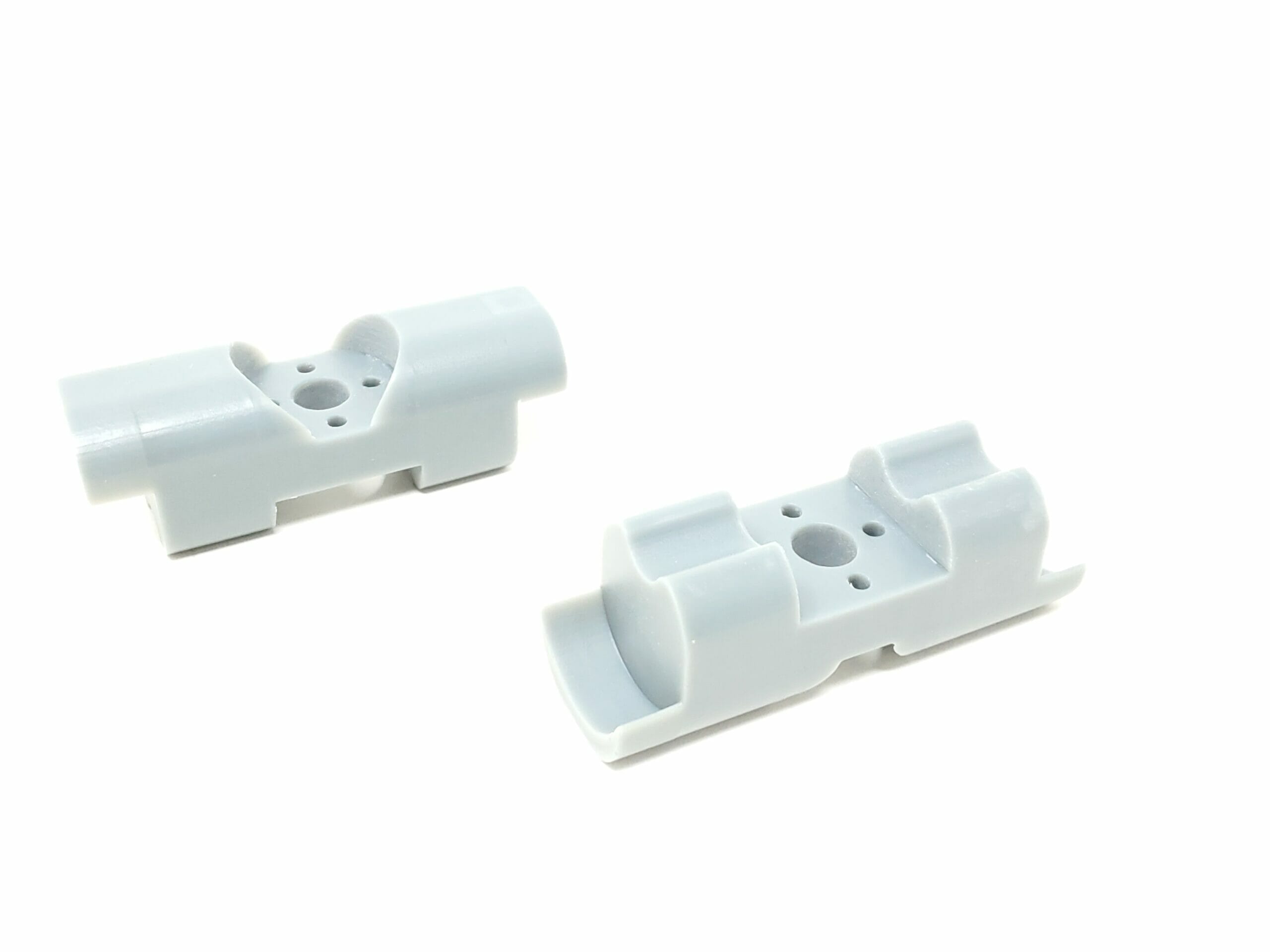
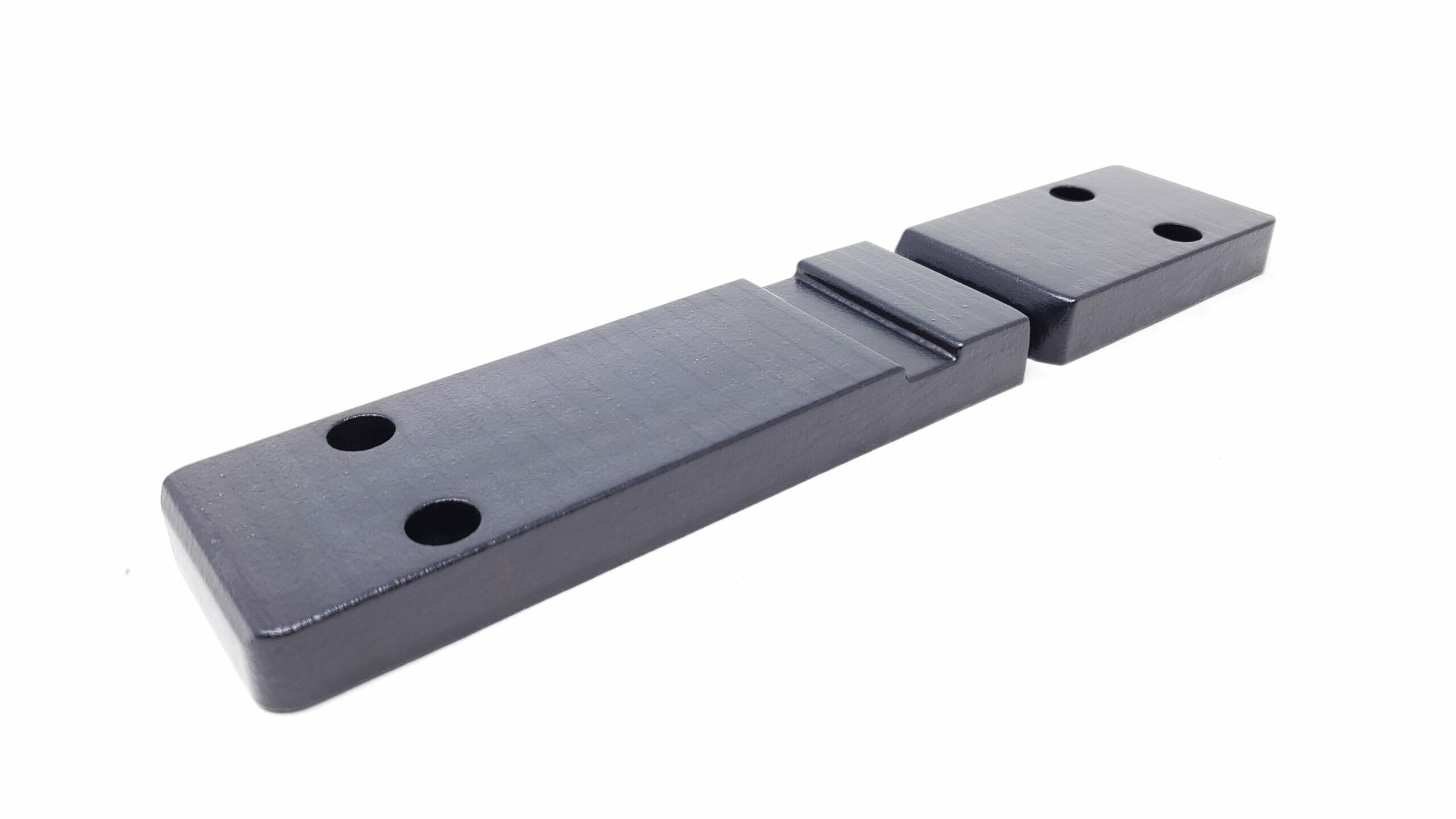
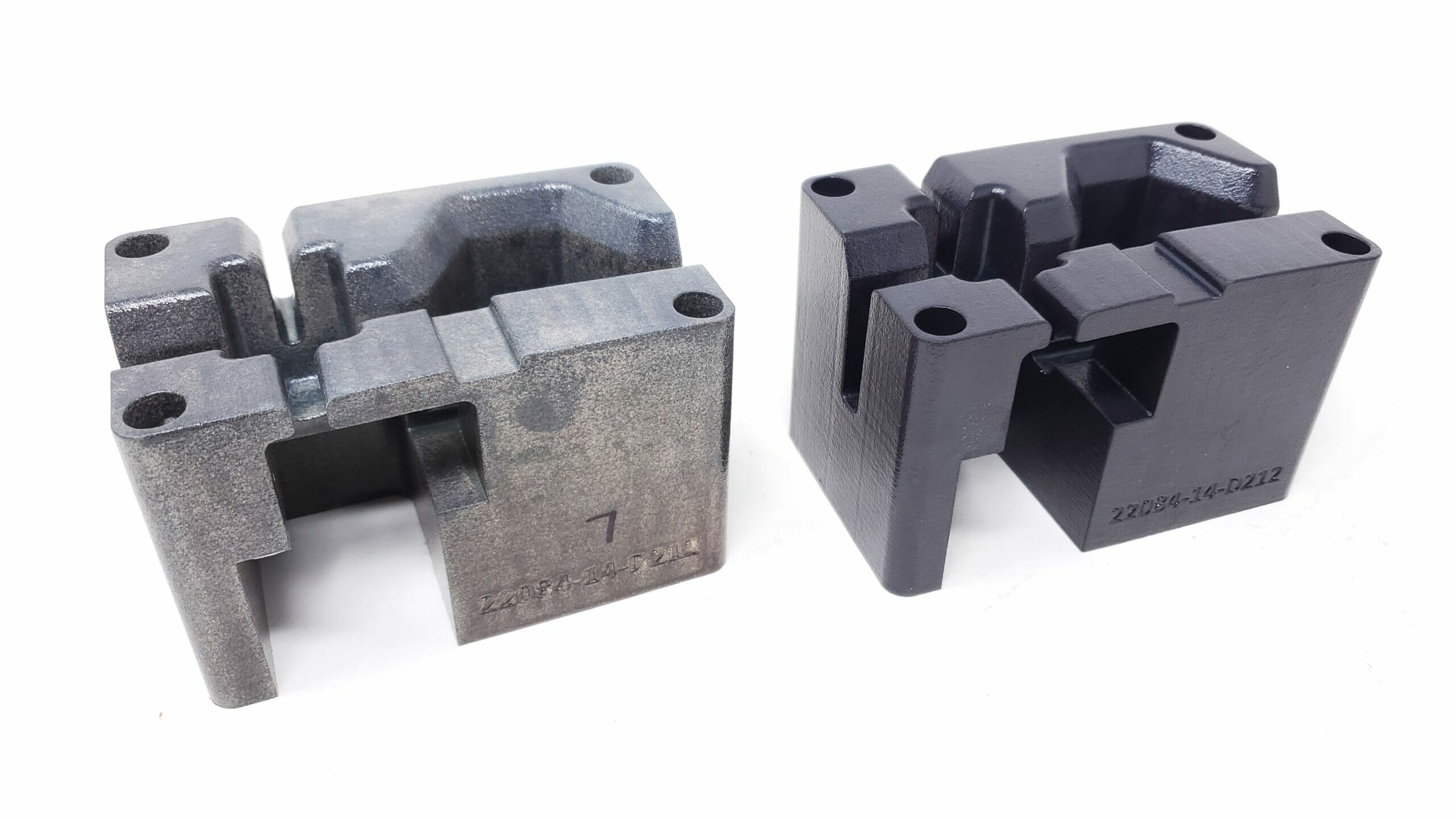
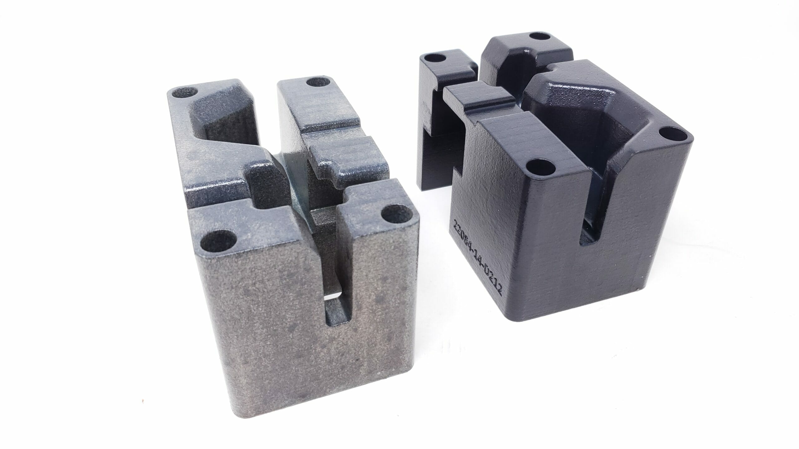
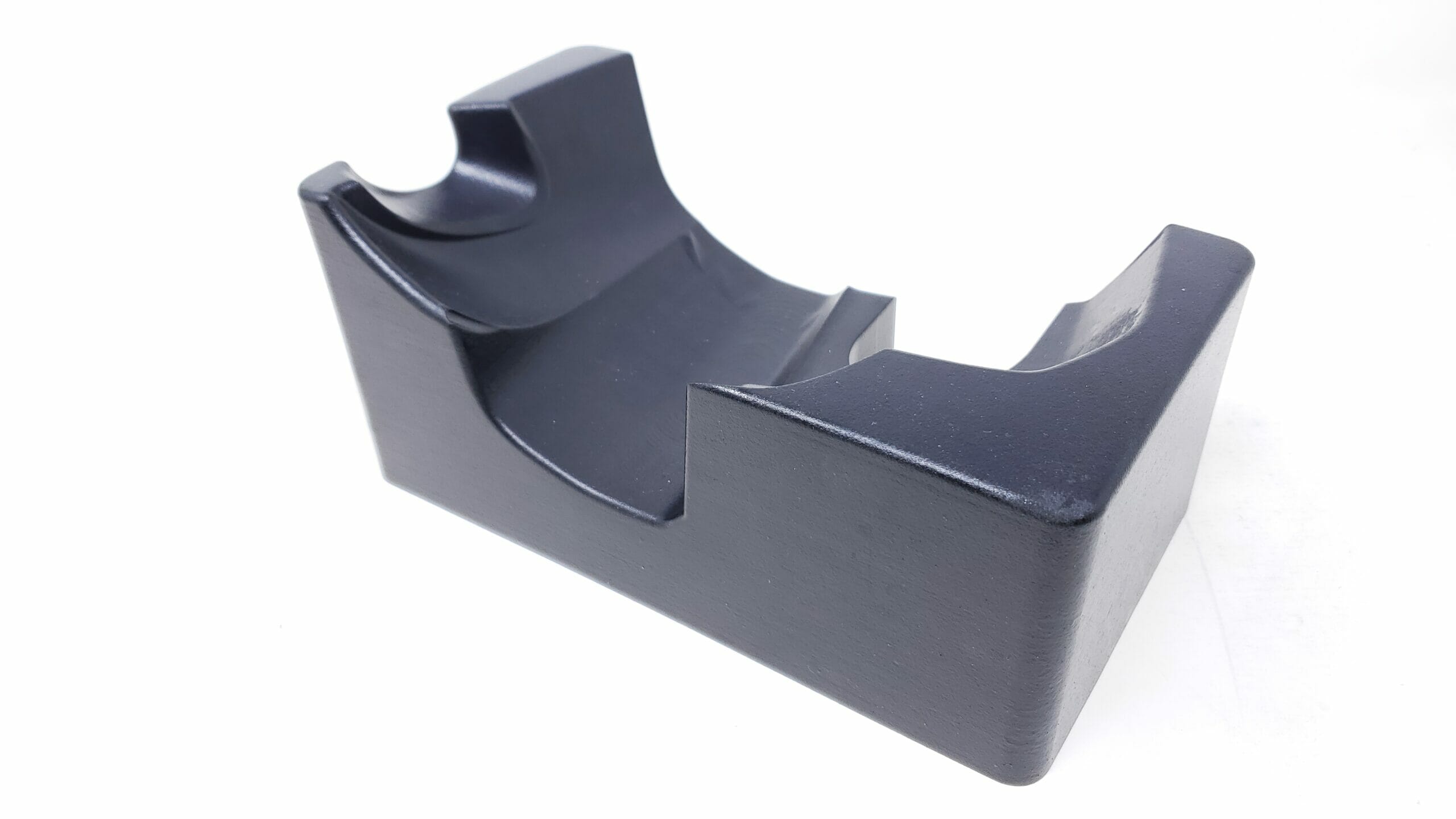
Example of a small nesting block that has dowels that are only 3″ apart so they are both true round dowel holes.
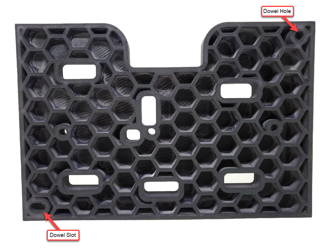
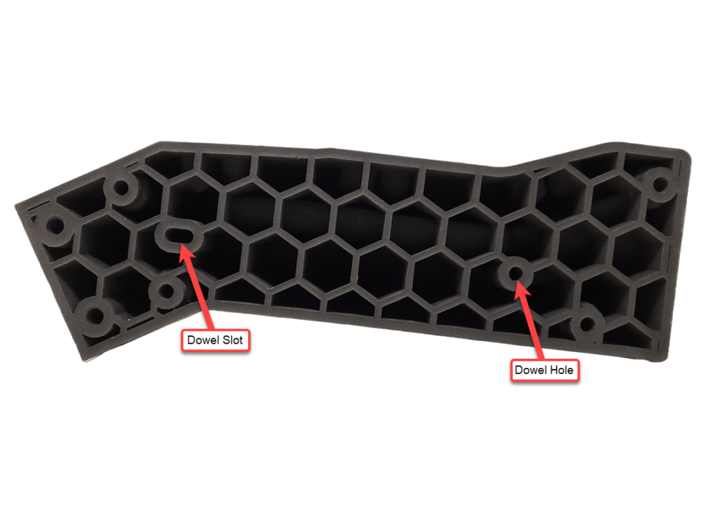
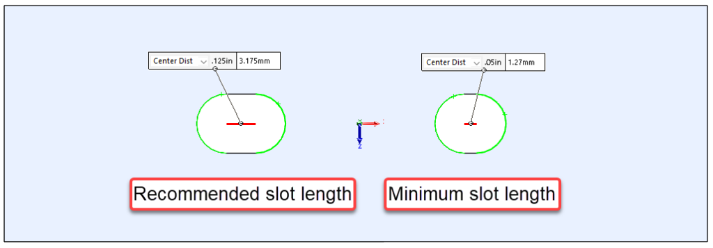
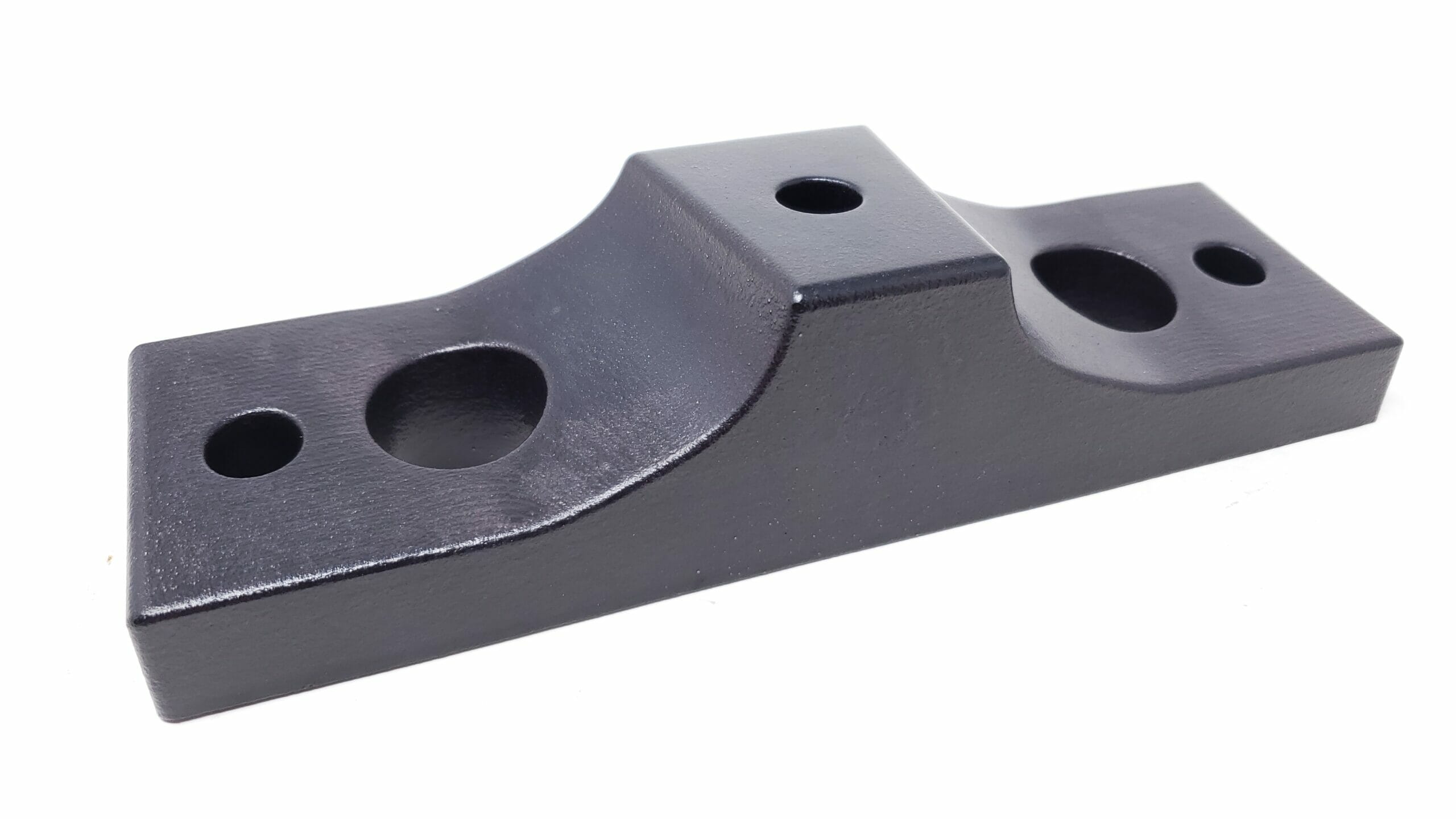
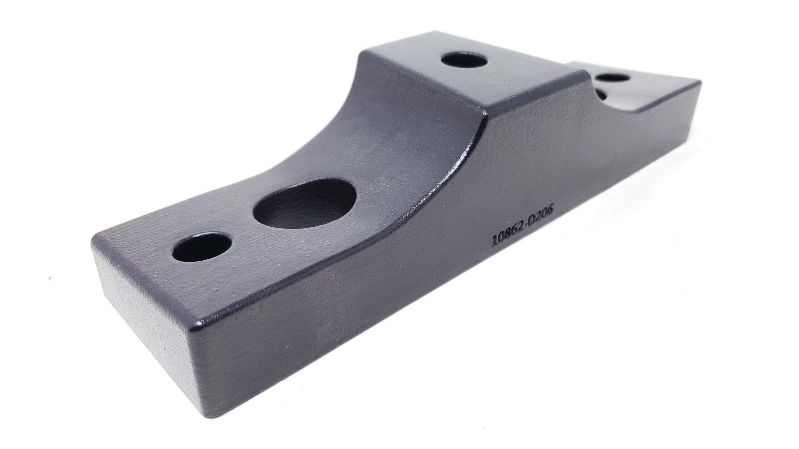
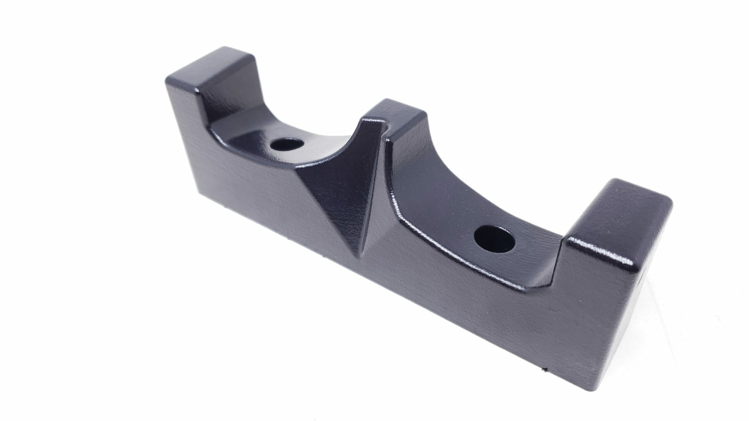
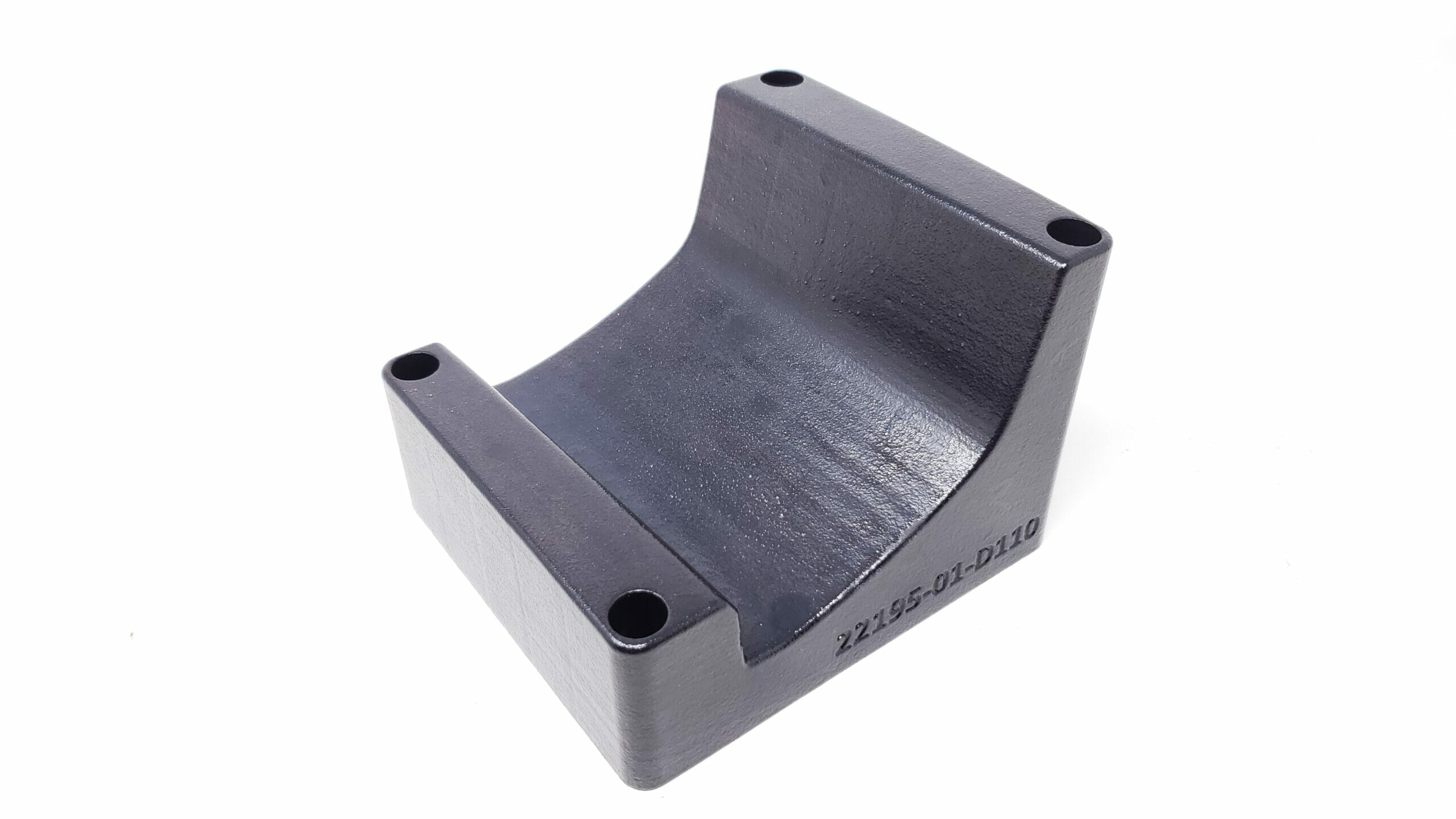
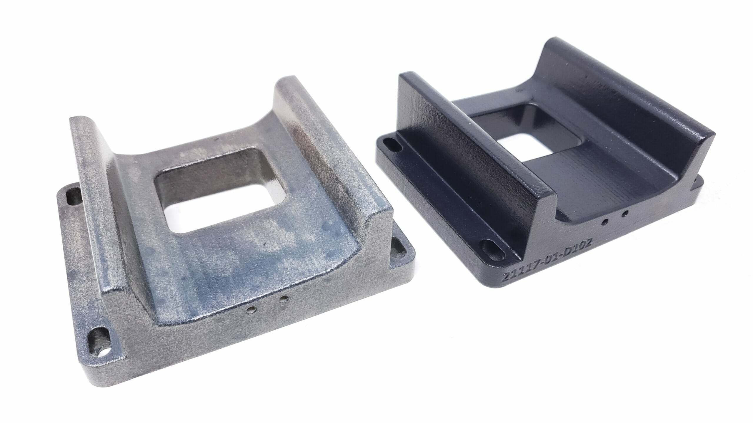
Rule #2: When you have a larger part that will have dowel holes further then 4″ apart then one of them should be turned into a dowel slot. The slot will allow for the natural inaccuracy of the printer but will still act as a positively locating feature so that the dowel system will work. If you were to use two round dowel holes in this situation there is a strong likelihood that when you went to assemble the parts the dowl pins would bind on the dowel holes in the opposite part during assembly and may break on the 3D printed parts due to misalignment.
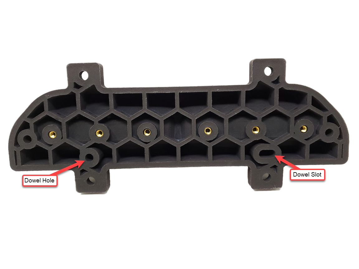
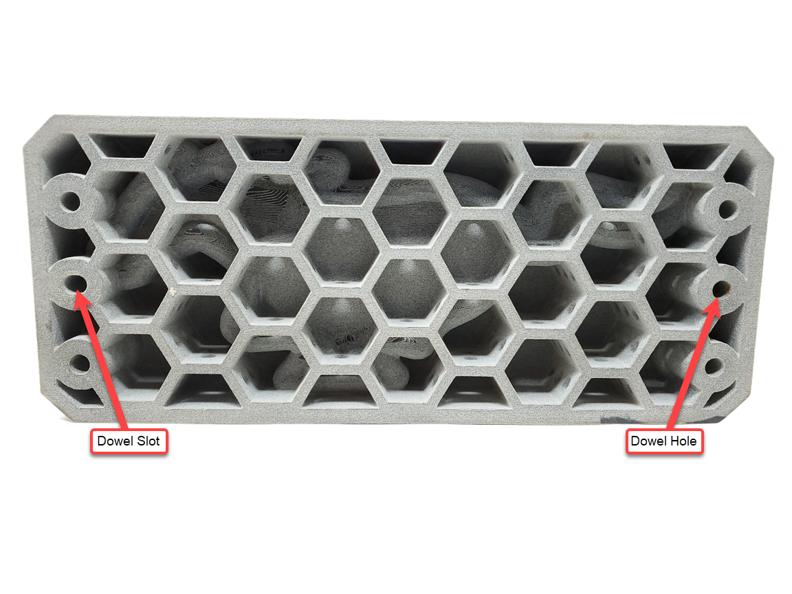
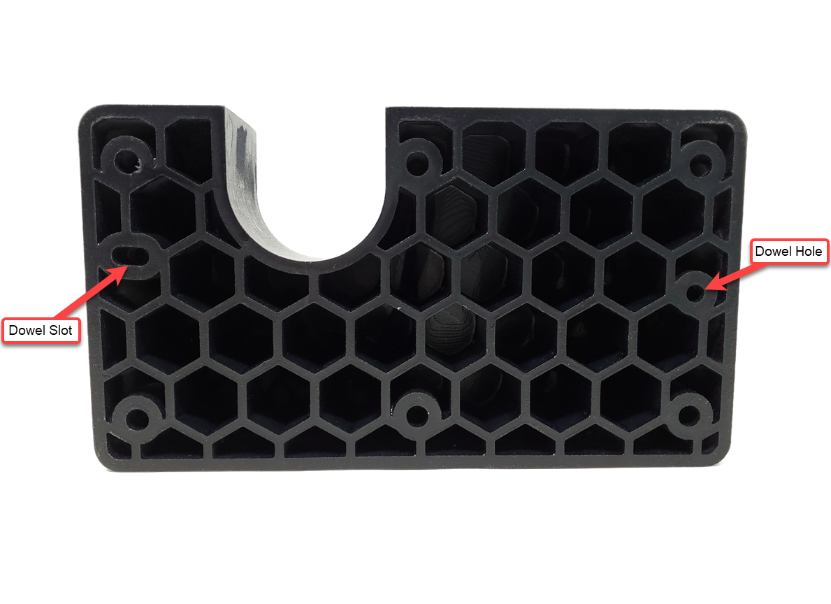
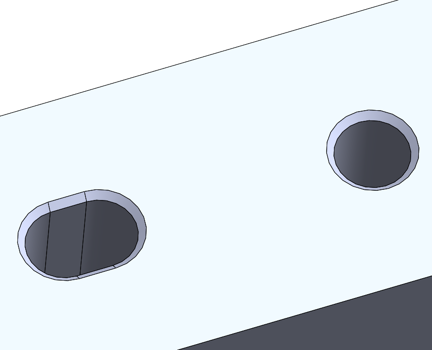
Example of a larger 3D printed nesting block that is using both a dowel hole and a dowel slot.
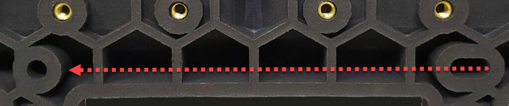
Rule #3: Make sure to point your dowel slot in the direction of its corresponding dowel hole on the other side of the part, this ensures that the slot will allow for misalignment during assembly as intended.
Rule #4: Your slot should be at a minimum of .125″ long, but if necessary can be as short as .05″.
Rule #5: If you need your dowel feature to be exactly on size (press fit, slip fit) undersize them by .025″ and plan on reaming them after printing. 3D printers do not currently have the accuracy needed to print dowel holes with these exact fits as required by some applications. Please keep in mind that not all 3DP material’s are machinable after printing so please reach out to our sales engineers to double check that the material you are getting your parts printed in is compatible with secondary machining.
Bonus Tip: With 3D Printing complexity on your parts is FREE so adding features like chamfers to your dowel holes will not add cost and can help with aligning dowel holes with their corresponding dowel pins.
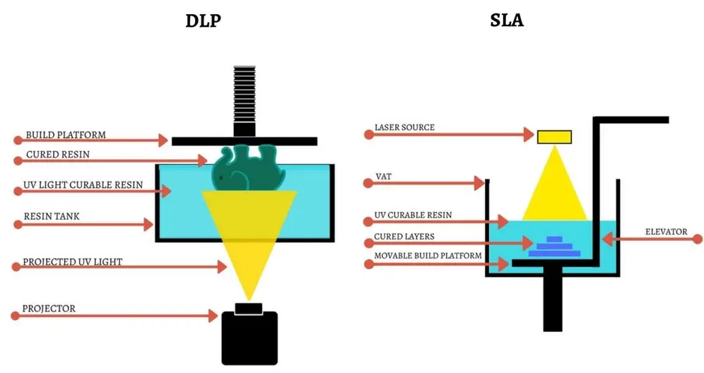
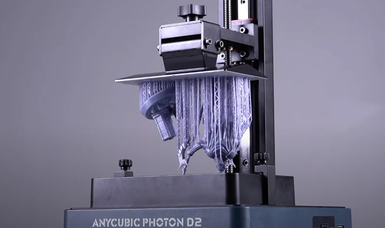
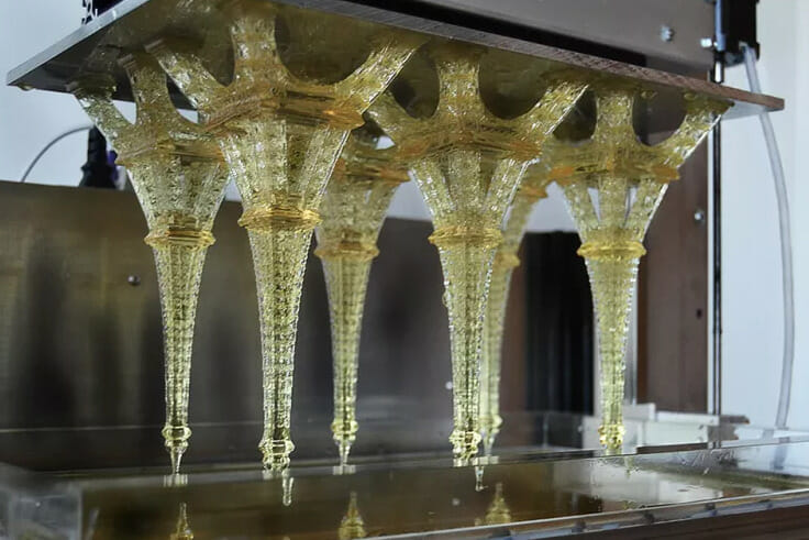
The DLP serves as the light projection component in DLP 3D printers, where it selectively illuminates the liquid resin to solidify it layer by layer.
DLP (Digital Light Processing) 3D printing technology utilizes a light source, typically a projector, to cure photopolymer resin layer by layer, resulting in the creation of three-dimensional objects. The working principle involves projecting an entire layer of the object onto a pool of liquid resin using a digital light projector. The light causes the resin to solidify, forming a thin layer. This process is repeated for each subsequent layer until the complete object is formed.
DLP compared to SLA 3D Printing technologies
One of the notable advantages of DLP 3D printing is its ability to achieve high-resolution prints with intricate details. This is made possible by the utilization of a digital light projector capable of displaying precise images. The high resolution enables the production of complex geometries and ensures fine surface finishes with high accuracy.
Another benefit of DLP 3D printing is its speed. Compared to other methods like FDM, DLP printing is generally faster. Since each layer is cured simultaneously, there is no need for the print head to move across the build area, resulting in shorter print times for certain objects.
DLP 3D printing is compatible with a wide range of photopolymer resins, allowing for versatility in material selection. These resins can be engineered to possess various properties such as flexibility, rigidity, transparency, or biocompatibility. This compatibility with different materials enables the production of parts tailored to specific applications.
Post-processing in DLP 3D printing involves removing the completed object from the build platform and washing it to eliminate excess resin. Depending on the specific resin used, additional curing or post-curing using UV light may be necessary to achieve desired mechanical properties and hardness.
The applications of DLP 3D printing are diverse and span various industries. It is commonly used in prototyping, dentistry, jewelry, art, custom components, and small-scale manufacturing. The technology’s ability to create intricate designs with smooth surfaces makes it ideal for producing visually appealing objects.
However, it is important to note some limitations of DLP 3D printing. It has a restricted build size compared to other additive manufacturing technologies. Additionally, printed objects may have lower mechanical strength and durability due to the resin-based nature of the process.
In summary, DLP 3D printing offers high-resolution prints, faster production times, and the ability to create intricate designs with smooth surfaces. Its applications are diverse, but it is important to consider the limitations associated with this technology.
DLP (Digital Light Processing) 3D printing is utilized in various industries for creating a range of parts. In automotive manufacturing, DLP 3D printing is used for rapid prototyping of customized components, allowing engineers to quickly iterate and test designs. It enables the production of intricate parts with precise details, helping automotive manufacturers improve the efficiency and accuracy of their development processes.
In addition to automotive applications, DLP 3D printing is also widely used in other sectors. For example, in the jewelry industry, it allows for the creation of detailed and intricate designs that are challenging to achieve through traditional methods. Artists and sculptors utilize DLP 3D printing to produce visually striking sculptures with fine details. Furthermore, DLP 3D printing is employed in the manufacturing of microfluidic devices, biomedical components, architectural models, and fashion accessories.
The versatility of DLP 3D printing makes it a valuable tool across various industries, including automotive, manufacturing, jewelry, art, and biomedical fields. It enables the production of highly detailed and customized parts, streamlines prototyping processes, and offers new avenues for creative exploration.
Common applications for DLP parts:
Jewelry
Biomedical devices
Housings
Automotive parts
Architectural models
Jigs and fixtures
DLP 3D Printing Materials:
LOCTITE IND406: Black – tough rigid and durable 3D printing resin that performs well in industrial applications requiring high temperature use. The material offers all-round strength, good impact resistance, and high elongation.
LOCTITE IND403: Black: Due to its high surface quality, dimensional accuracy and temperature resistance this tough resin is ideal for interior applications in automotive and mold production.
EPX 82: Black – Combines functional toughness, stiffness, and temperature resistance, making it useful for a variety of automotive, industrial, and consumer applications. Recommended general purpose material.
Key Material Facts:
EPX 82 combines functional toughness, stiffness, and temperature resistance, making it useful for a variety of automotive, industrial, and consumer applications.
RPU 130: Black – strong and tough engineering polyurethane offering a unique combination of durability, impact resistance, and performance at elevated temperatures
Key Material Facts:
RPU 130 is a strong and tough engineering polyurethane offering a unique combination of durability, impact resistance, and performance at elevated temperatures.
EPU 41: Black – 71A rubber, production-grade elastomeric material that is especially well-suited for elastomeric lattices where high resiliency is needed
Key Material Facts:
EPU 41 is a production-grade elastomeric material that is especially well-suited for elastomeric lattices here high resiliency is needed.
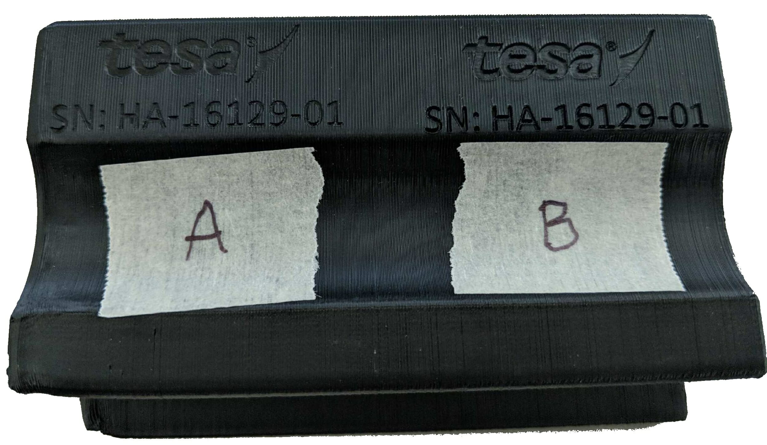
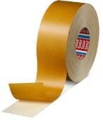
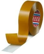
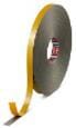
Doubled sided adhesive tape can be used to attach 3D Printed parts to each other. We have done some testing with our preferred tape vendor (tesa tape) on which of their generally available tapes worked the best for both raw Nylon 12 (PA-12) parts as well as Nylon 12 parts that had been coated in Cerakote. Below you will find the results of this testing as well as clickable links to sources where this tape can be purchased.
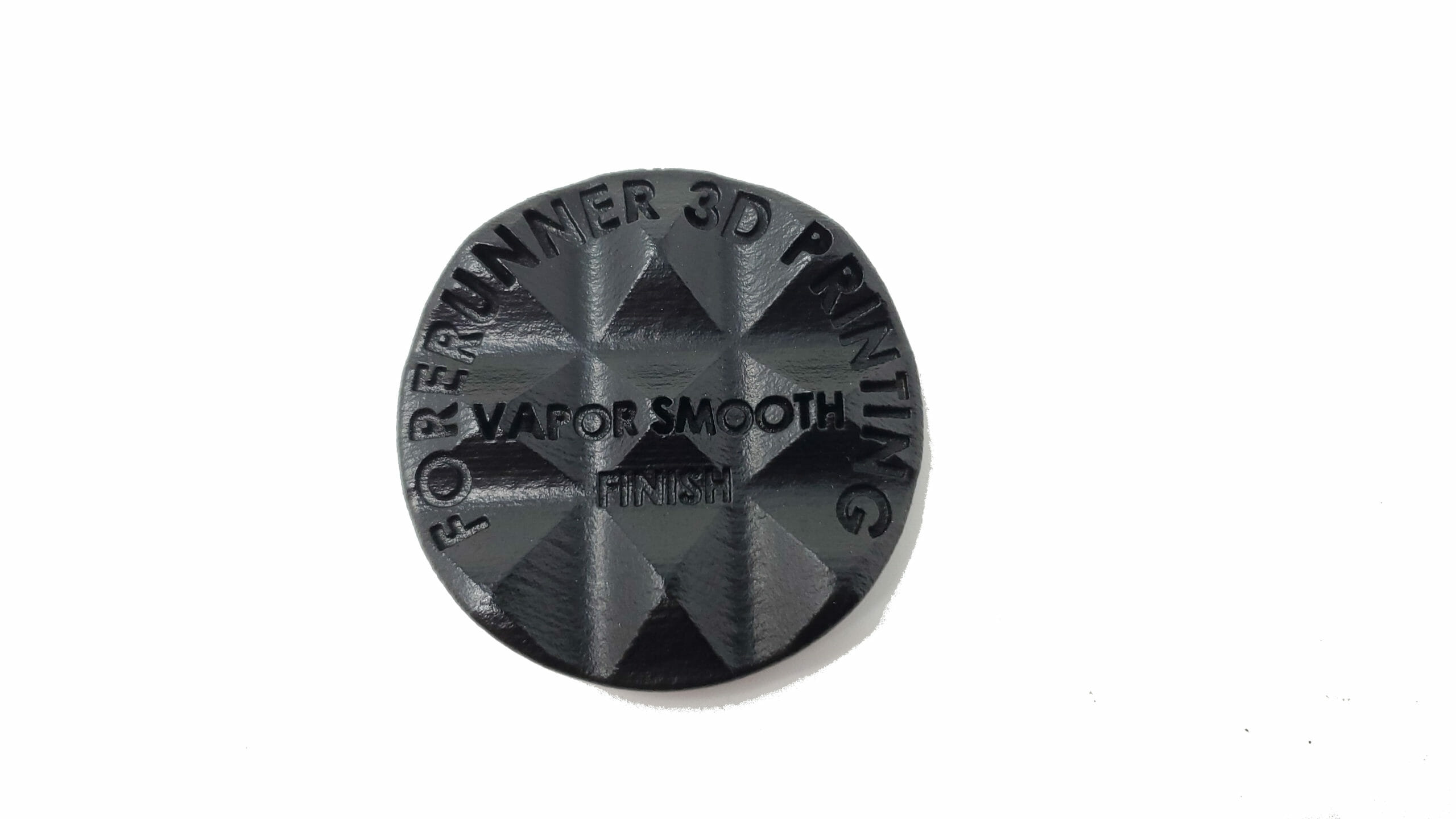
Vapor Smoothing Finish Options For 3D Printed Parts
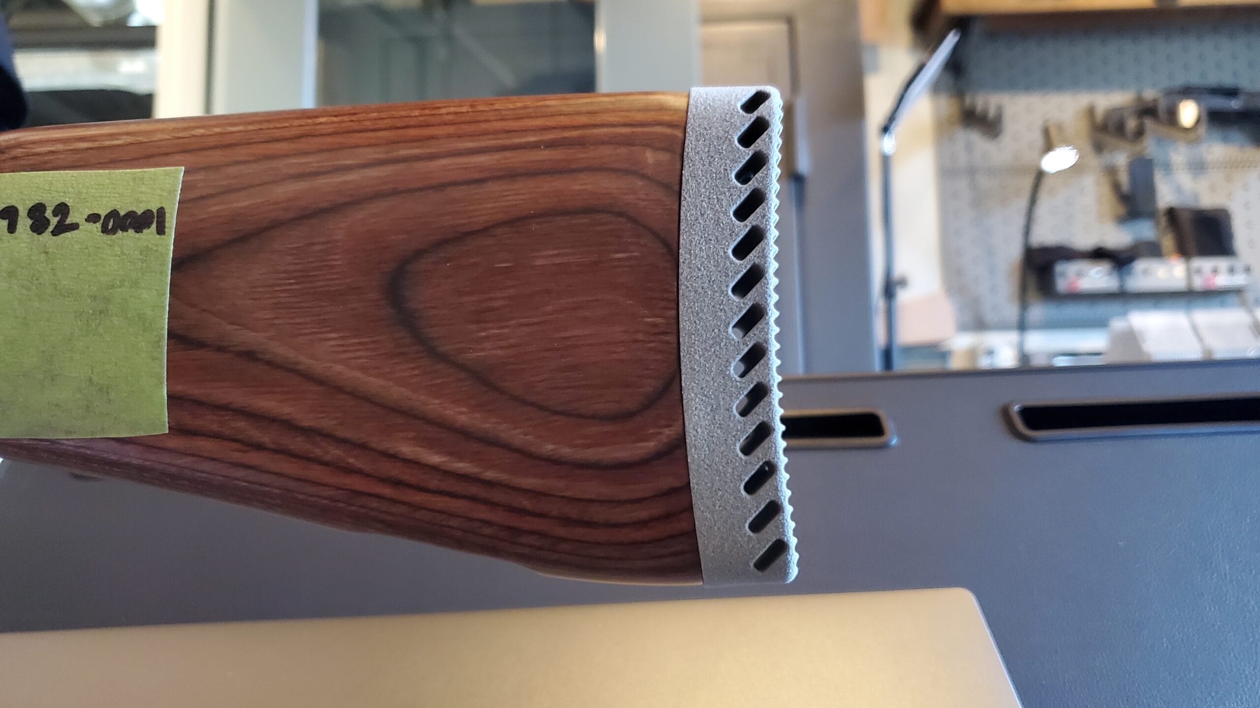
The Vapor Smoothing process is a chemical surface smoothing method that improves the part performance, seals the surface, and offers a smooth / glossy look and feel. One of the popular applications for this finish is smoothing TPU nesting that will be holding parts with extremely delicate class A finish’s like Matte Black. The smoothing process prevents fine TPU powder from rubbing off the surface of the nesting and ending up on the surface of the part that is resting on it. This chemical smoothing process fully seals the TPU part and prevents this from happening:
We utilize both a proprietary inhouse process for TPU smoothing as well as traditional smoothing machines from AMT for other materials like Nylon 12:
Increased mechanical properties – Due to the removal of surface porosity, extensive testing demonstrates that vapor smoothed demonstrated no loss in Ultimate Tensile Strength (UTS) with an increase in Elongation at Break (EAB).
Dimensional accuracy – The process does not degrade the mechanical properties of the parts. After vapor smoothing, parts exhibit no more than a 0.4%-dimensional change irrespective of the desired finish level.
Seals against liquid & gas intake – The vapor smoothing process completely seals the surface, eliminating liquid or gas intake.
Reduction in bacteria growth – Tests have shown the reduction of bacteria growth and attachment on parts that have been chemically vapor smoothed.
Reduced friction – due to the surface of the part being smoothed out / sealed it allows for the surface friction of the part rubbing against other parts to be lower.
Examples of Nylon and TPU rubber parts that have been Vapor Smoothed:
Here at Forerunner 3D printing we have developed a proprietary process that allows us to smooth Lubrizol Estane® 3D TPU M95A-545 OR UV Rubber material, we are one of only 2 companies in the world currently able to print parts in this material and also vapor smooth them inhouse.
Another option for a part that has been Vapor Smoothed is to combine it with another coating process like our Cerakote coating process. The following are examples of a vapor smoothed part that has had Cerakote applied to it:
*Note: Food safe applications need to be evaluated on a case by case basis and the customer is responsible for certifying their own application meet all food safety requirements.
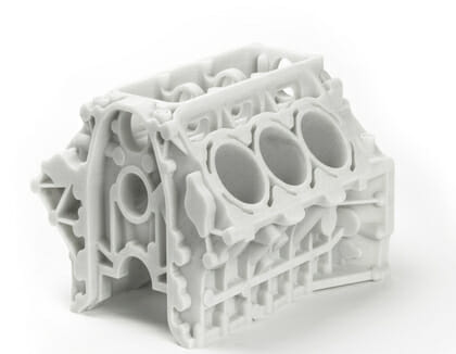
Selective laser sintering (SLS) was developed and patented by Dr. Carl Deckard and Dr. Joe Beaman at the University of Texas at Austin in the mid-1980s. Deckard and Beaman were involved in the resulting start up company DTM, established to design and build the SLS machines. In 2001, 3D Systems, the biggest competitor to DTM and SLS technology, acquired DTM. This page discusses in detail the advantages of using SLS technology to 3D print parts. It explains the most common SLS materials, offers rules for designers to follow when printing with SLS, and also shows a gallery of various parts that were produced using SLS 3D Printing equipment.
SLS machine running, parts can be seen being traced and hatched as the laser melts the powder.
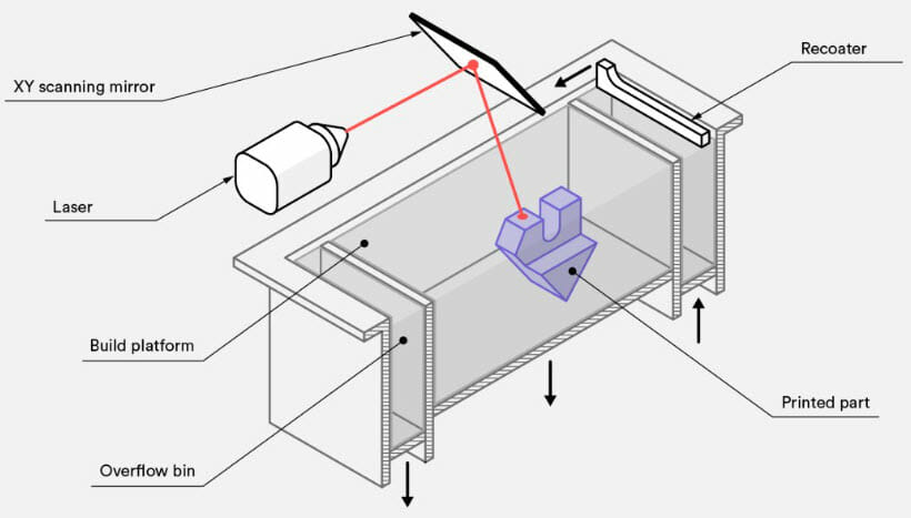
Selective laser sintering (SLS) is an additive manufacturing (AM) technique that uses a laser as the power and heat source to sinter a powdered material (typically nylon or other plastic). At the start of a new layer the print bed is dropped by 0.004”- 0.006” depending on the material being printed. The recoater picks up a load of freshly heated raw powder from the material storage bin and moves across the build platform filling in the thickness that the build platform has been dropped with the fresh hot powder. At this point the laser comes on and begins tracing and hatching that slice of the parts being printed. The part slice is defined by a 3D model that has been loaded into the machines build management software. As the laser sweeps across the areas being sintered it is binding the material together to create a solid structure. After the powder is sintered, the parts must be allowed time to cool. Depending on the size of the parts, cooling time usually takes equally as long as the time it took to print the job in the first place. For that reason SLS jobs usually have longer lead times (at least 1 day for production and 1 day for cooling) when compared to other printing technology like SLA, PolyJet, or FDM. For extremely large SLS parts (something larger than 20″ x 20″ X 10″), printing can span several days followed by several days of cool down time.
Selective Laser Sintering uses high-powered lasers to sinter powdered material, binding it together to create a solid structure. This printing process is considered to be a support free process. The parts are supported by unsintered powder that is left over after that layer has been sintered. Once the printing of that build is complete, the part(s) are removed from the block of loose unsintered powder they are trapped inside of and cleaned by hand and using air jets and a bead blaster to remove all the excess powder that is still clinging to the surface of the part.
SLS is known for having a relatively good level of accuracy, cheap raw material costs, the ability to easily make complex geometries without supports, parts that are very strong, and producing parts that can handle high temperatures (300F+). This makes it an incredibly useful technology for a broad range of applications in things like prototype parts, investment casting patterns, automotive parts, and wind tunnel models. It is also commonly used for low volume manufacturing of end use parts for aerospace, military, medical, pharmaceutical, and electronics hardware. On a shop floor, SLS can be used for rapid manufacturing of tooling, nesting, and fixtures.
Bio compatible according to EN ISO 10993-1 and USP/level VI/121 °C
Typical applications of this material are things like high quality fully functional plastic parts. Due to the excellent mechanical properties of this material it is often used as a substitute for Nylon injection moulding plastics. The biocompatibility of this material allows for its use on prostheses and the high abrasion resistance it possesses allows for part with movable connections.
PA 3200 GF (PA12-GB): White, glass bead filled polyamide 12 powder, characterized by excellent stiffness in combination with good elongation at break
PA 3200 GF is a whitish, glass-filled polyamide 12 powder, which is characterised by an excellent stiffness in combination with good elongation at break. Laser-sintered parts made from PA 3200 GF possess excellent material properties:
Color: White
High stiffness
High mechanical wear-resistance
Good thermal loadability
Excellent surface quality
High dimensional accuracy and detail resolution
Good processability
Excellent long-term constant behaviour
A typical application for PA 3200 GF is for end use parts within the engine bay of cars, for deep-drawing dies or any other application which requires particular stiffness, high heat distortion temperature and low abrasive wear.
DuraForm PAx Natural: High impact, high elongation, high recyclability SLS material with properties similar to injection molded polypropylene for tough, lightweight, production-grade parts.
DuraForm PAx Natural is a nylon copolymer that offers properties similar to injection molded plastic and features high impact resistance with high elongation at break in any direction, including Z. Engineered for easy processing and high recyclability, DuraForm PAx Natural is ideal for functional prototypes and end-use parts with good mechanical properties and long-term stability.
Color: Natural
Durable and tough for true functional plastic parts
Excellent long-term stability; 5+ years indoor for mechanical properties and color
Capable of being used for 3D printed living hinges
Enclosures requiring high impact and high toughness
Complex parts with interior components can be built without trapping the material inside and altering the surface from support removal.
Due to the reliable mechanical properties, parts can often be substituted for injection molded parts
For PA-12 and PA-12 GB the largest allowable part size is: 27.6″ x 15″ x 22.9″ (700mm x 380mm x 580mm), Layer Thickness: 0.003″ – 0.006″
For DuraForm PAx the largest allowable part size is: 15″ x 13″ x 18″ (550mm x 550mm x 460mm), Typical Layer Thickness: 0.004″
Accuracy: +/- .015″ for the first 1 inch, +/- .010″ per inch thereafter
Like with injection molding, if your part can have a consistent wall thickness throughout its design the part will print more accurately and with less warp / twist.
For long, thin parts: use ribbing to mitigate warping risks.
Wall thickness: To ensure a successful 3D print, minimum thickness should be between 0.8mm.
Hole size: All holes should be larger than 1.5mm in diameter.
Feature size (pins, protruding features, etc.): A minimum of 0.8mm is recommended.
Embossed and engraved details: To ensure small details are visible: Make minimum engraving / embossing 1mm.
Text: For readability ensure minimum font height is 2mm (font size 14), sans serif font is recommended.
SLS can produce many functional features, including axles, threads, tanks and hinges. Coupled with the range of available engineering polyamides, this makes SLS commonly used to produce end-use parts.
Gaps for Mating Parts: 0.5 mm clearance between features
3D Printing / Additive Manufacturer For The Firearms Industry
Forerunner 3D Printing holds a Federal Firearms License for Manufacturing (FFL 07) as well as a Special Occupational Taxpayer for Manufacturing (SOT 02) and specializes in working with firearms customers to produce both their prototype and end use production parts. We offer a wide range of inhouse services to assist our customers with their projects which include Engineering, Reverse Engineering, Metrology / Inspection, Cerakote, Deep Laser Engraving, and 3D Printing.
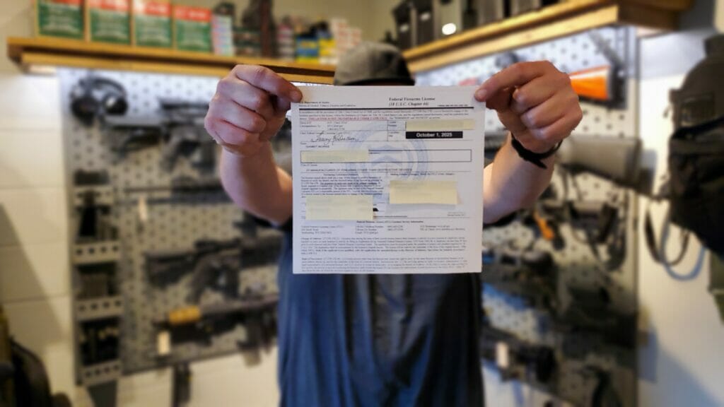
F3DP Owner Paul DeWys standing in his office displaying FFL07, Paul has always been passionate about designing and building firearms. This attitude extends to the rest of the team at F3DP as well and is the reason we have pursued being a source for 3D Printing for the Firearms Industry.
Why use 3D Printing?
3D printing with polymers eliminates engineering constraints that are prominent in traditional design-for-manufacture projects. The emergence of this new manufacturing technology has lead to innovations that allow for weight reduction, superior performance, and new advancements in firearms and tactical gear. 3D Printing is also a good way to greatly reduce a companies time to market by shortening lead times for prototypes and also allowing for the bridge / low volume production of parts while traditional tooling is built.
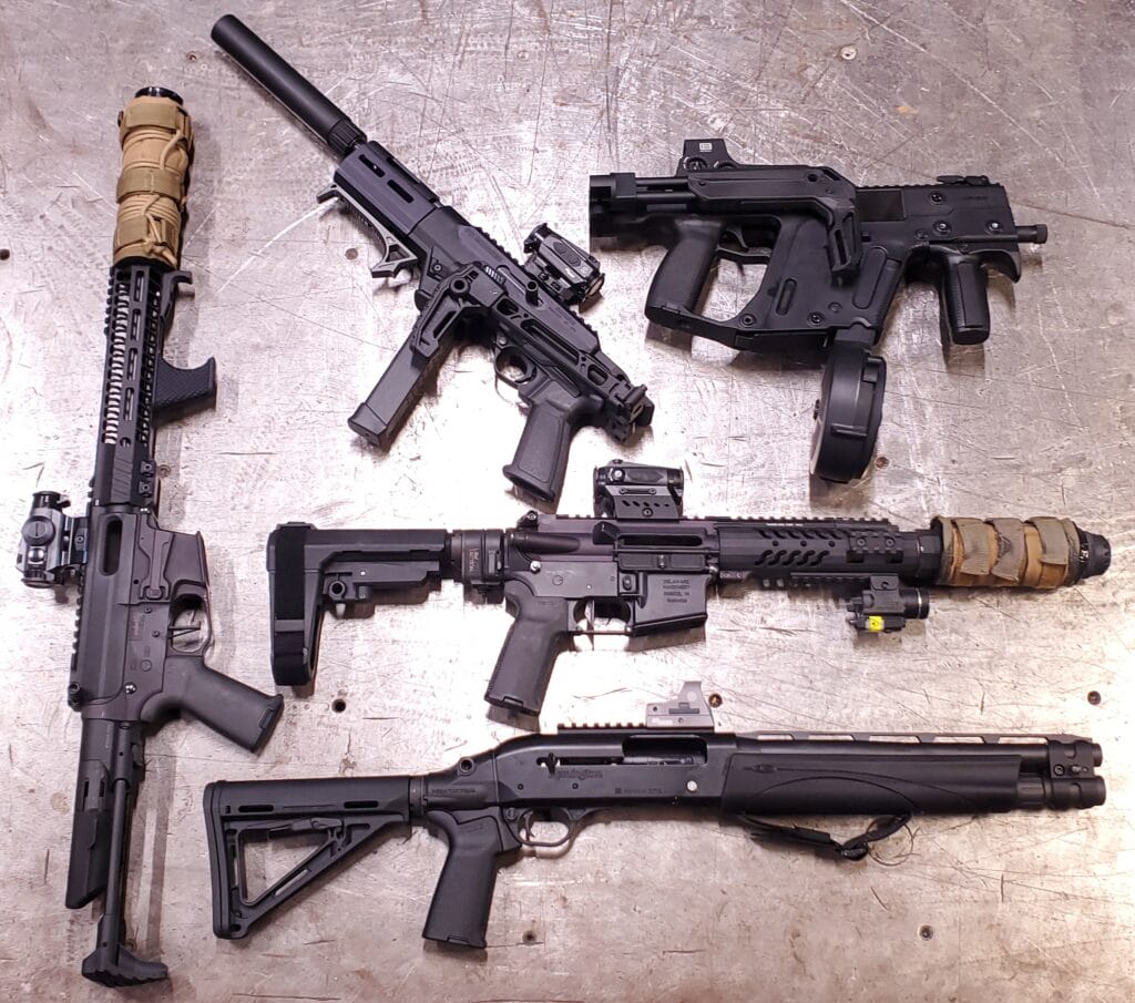
We have printed a range of parts for customers in the defense and firearms industry’s over the years including:
Night vision parts
Receivers / mag wells
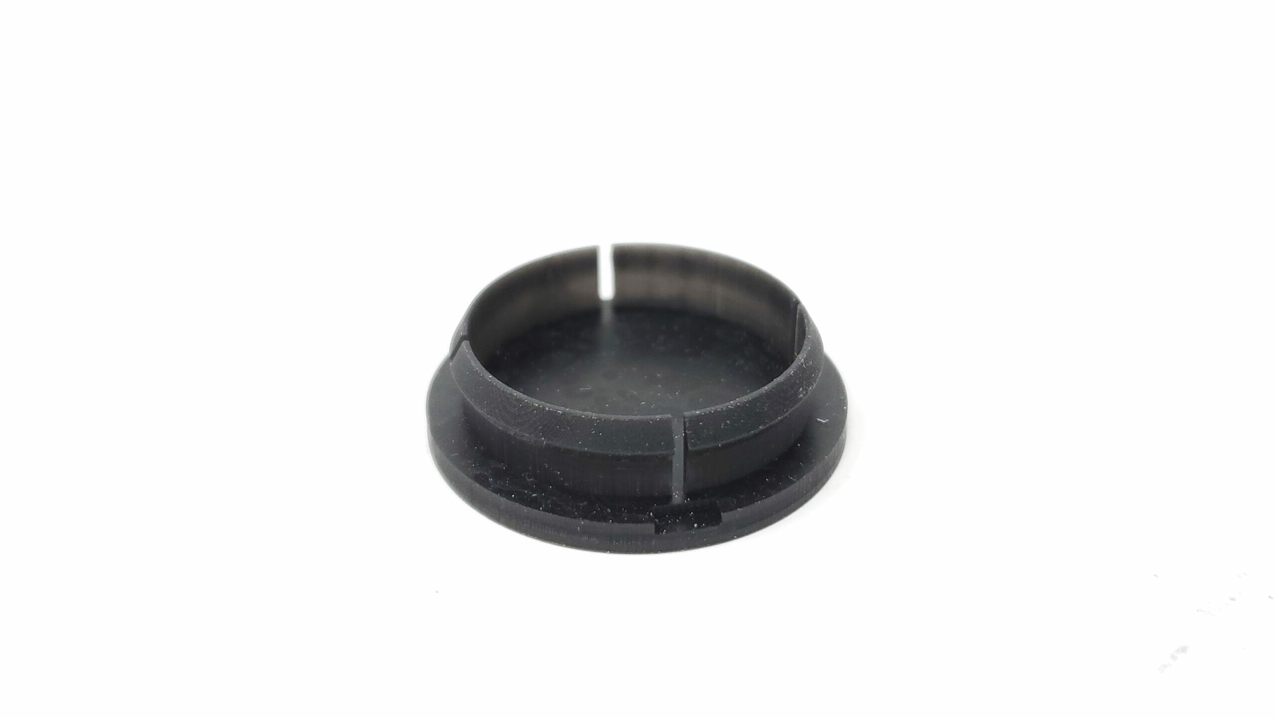
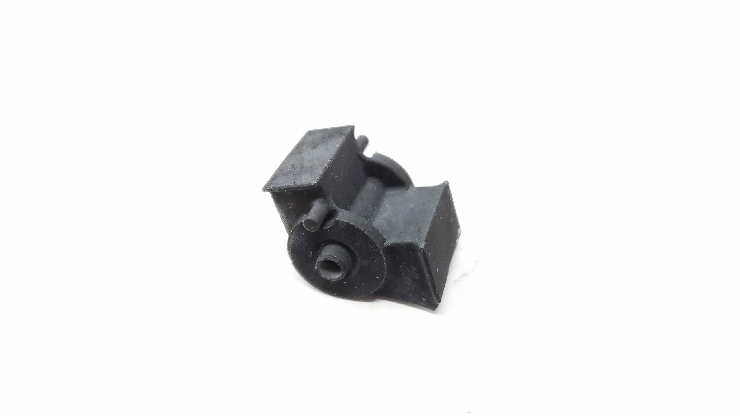
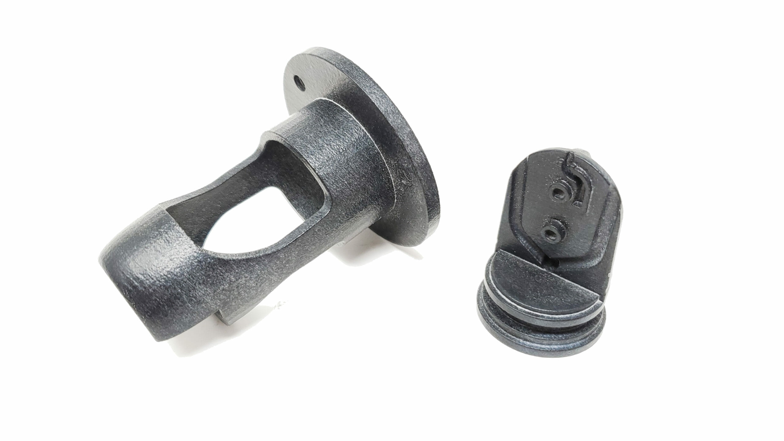
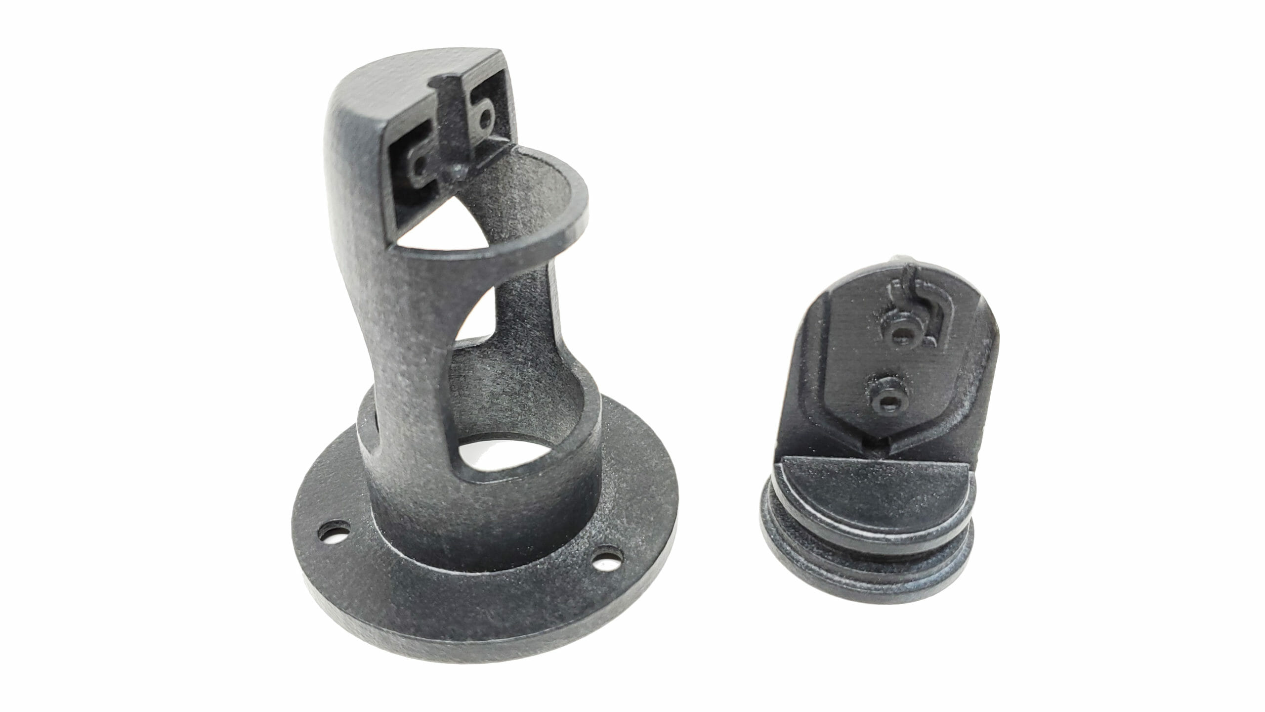
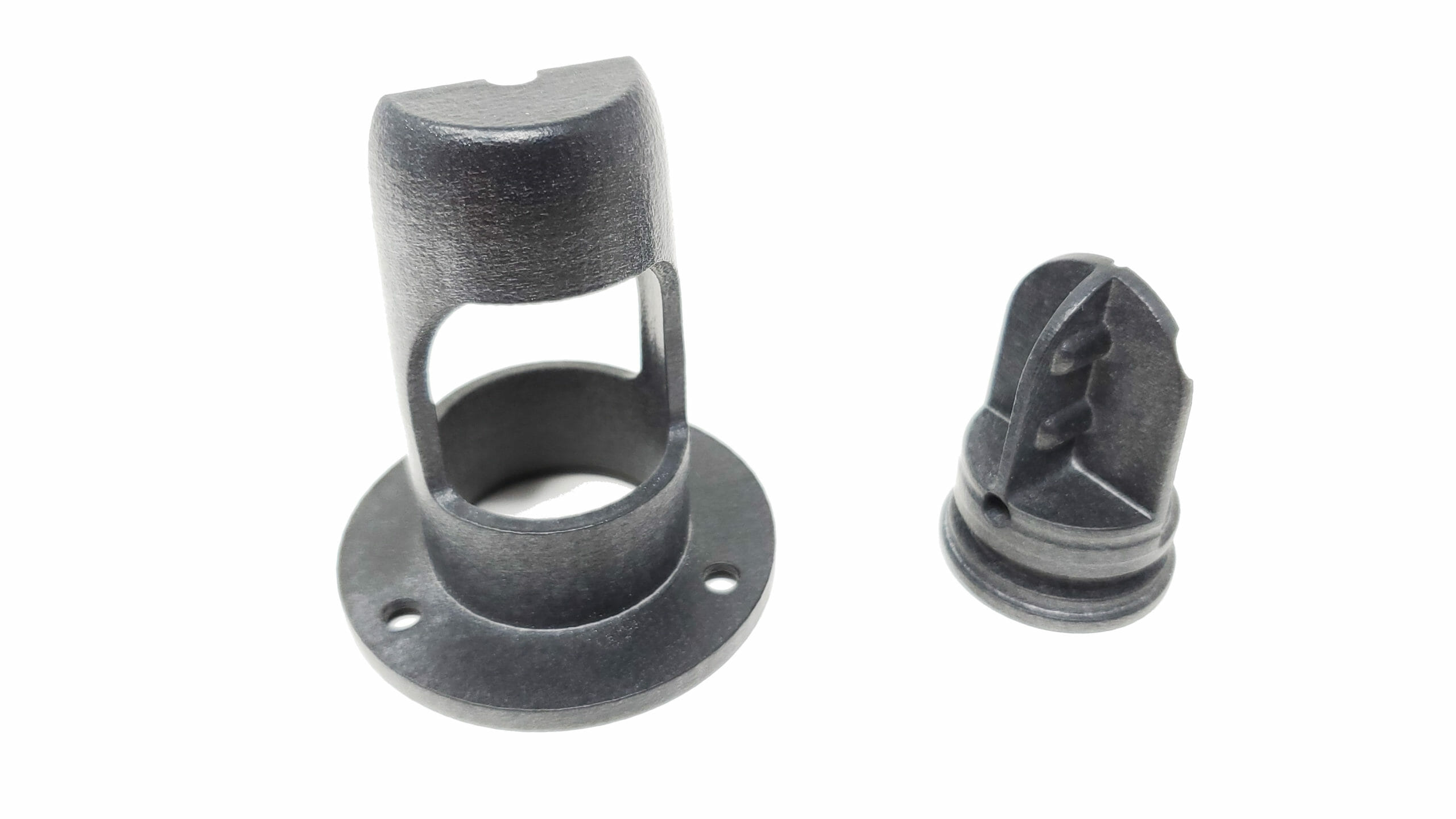
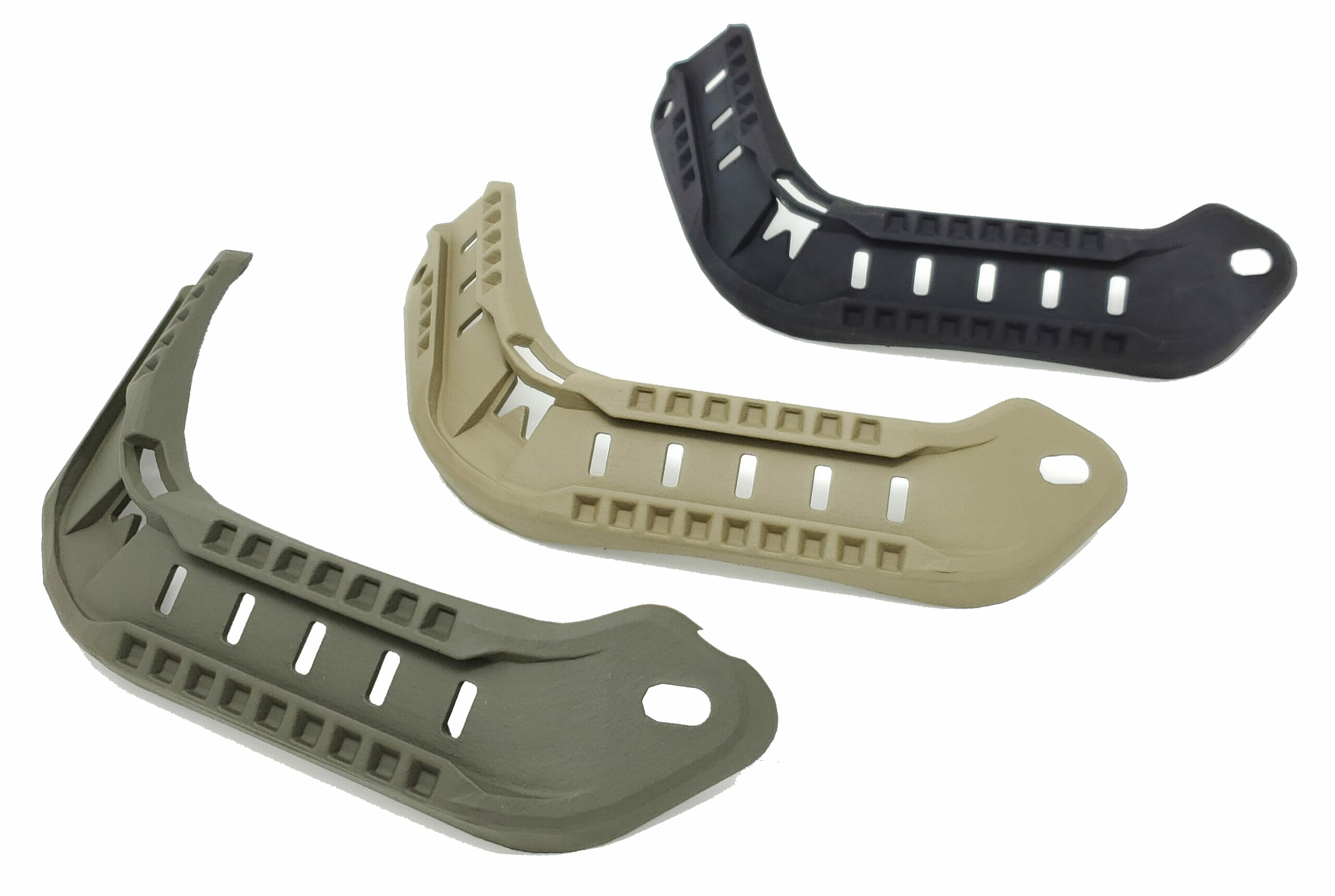
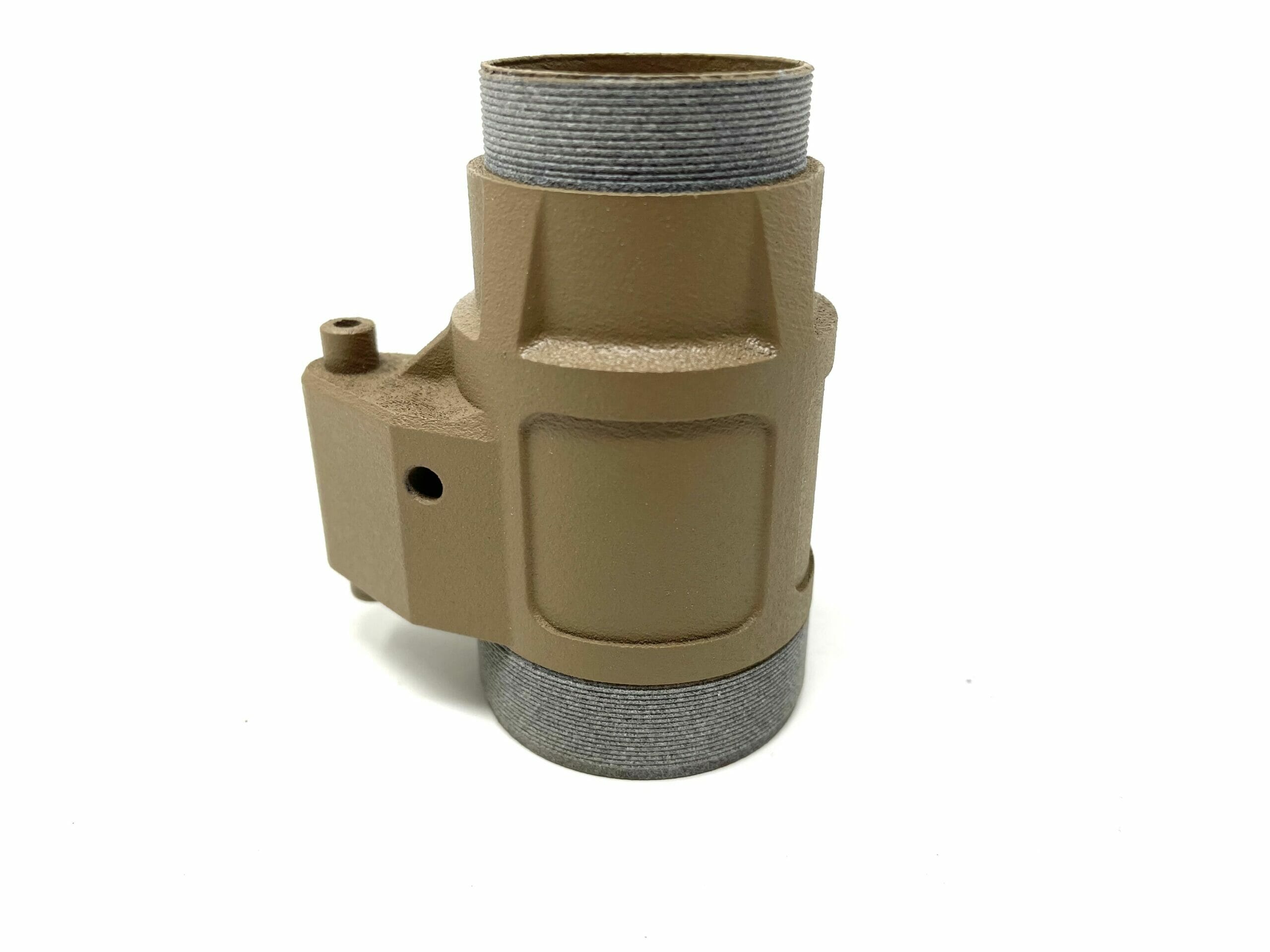
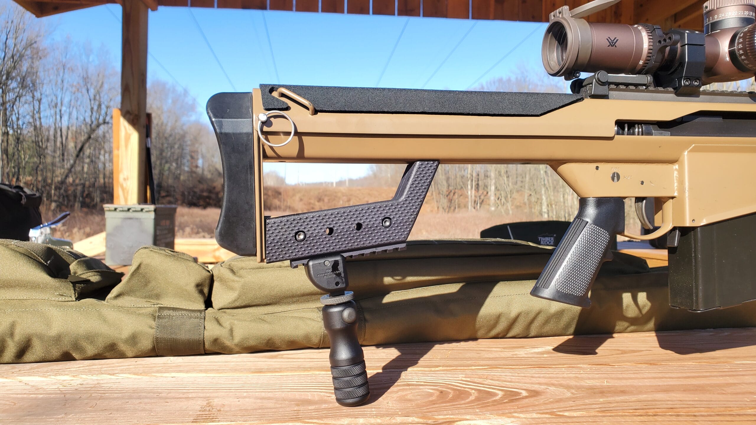
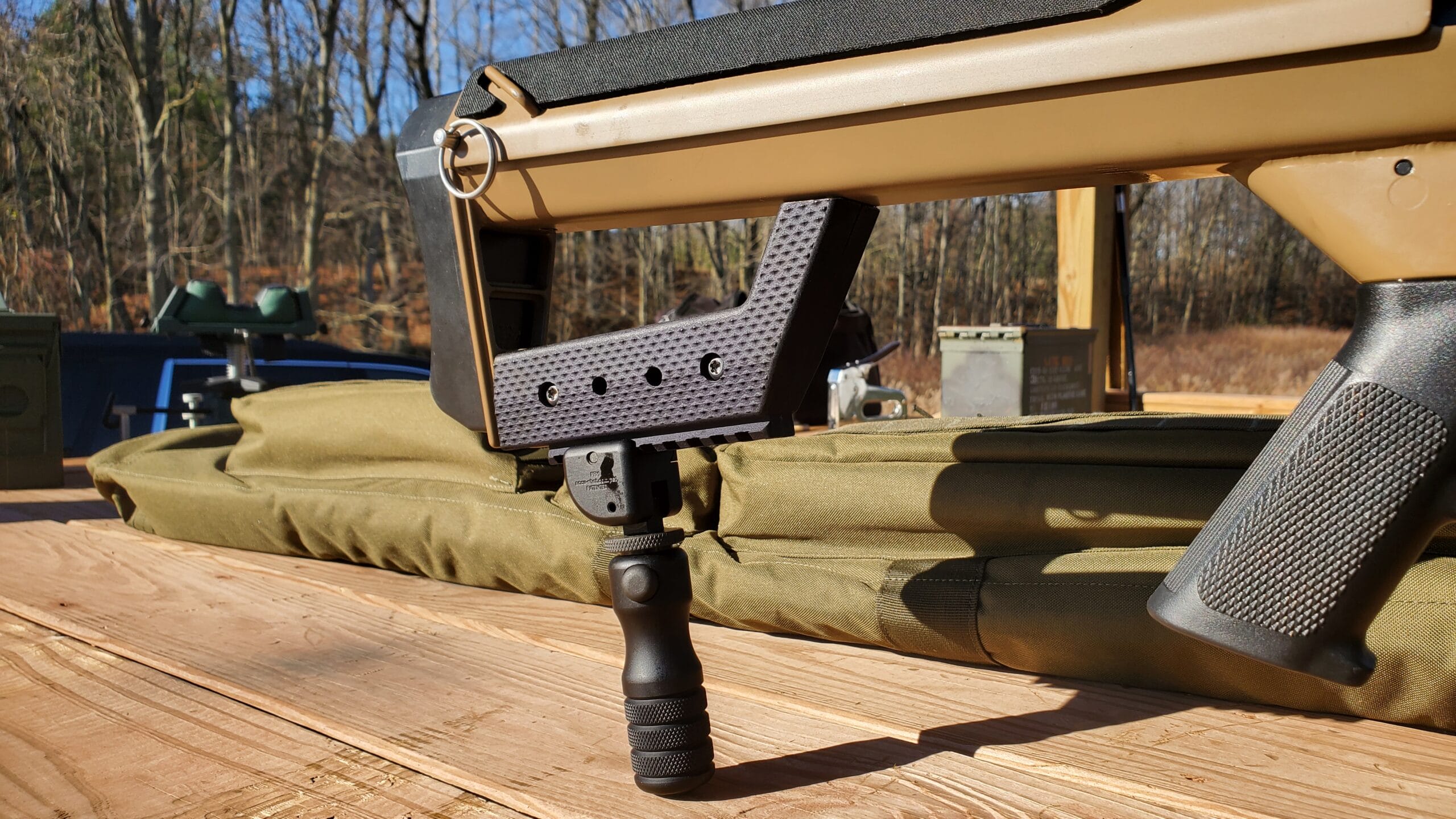
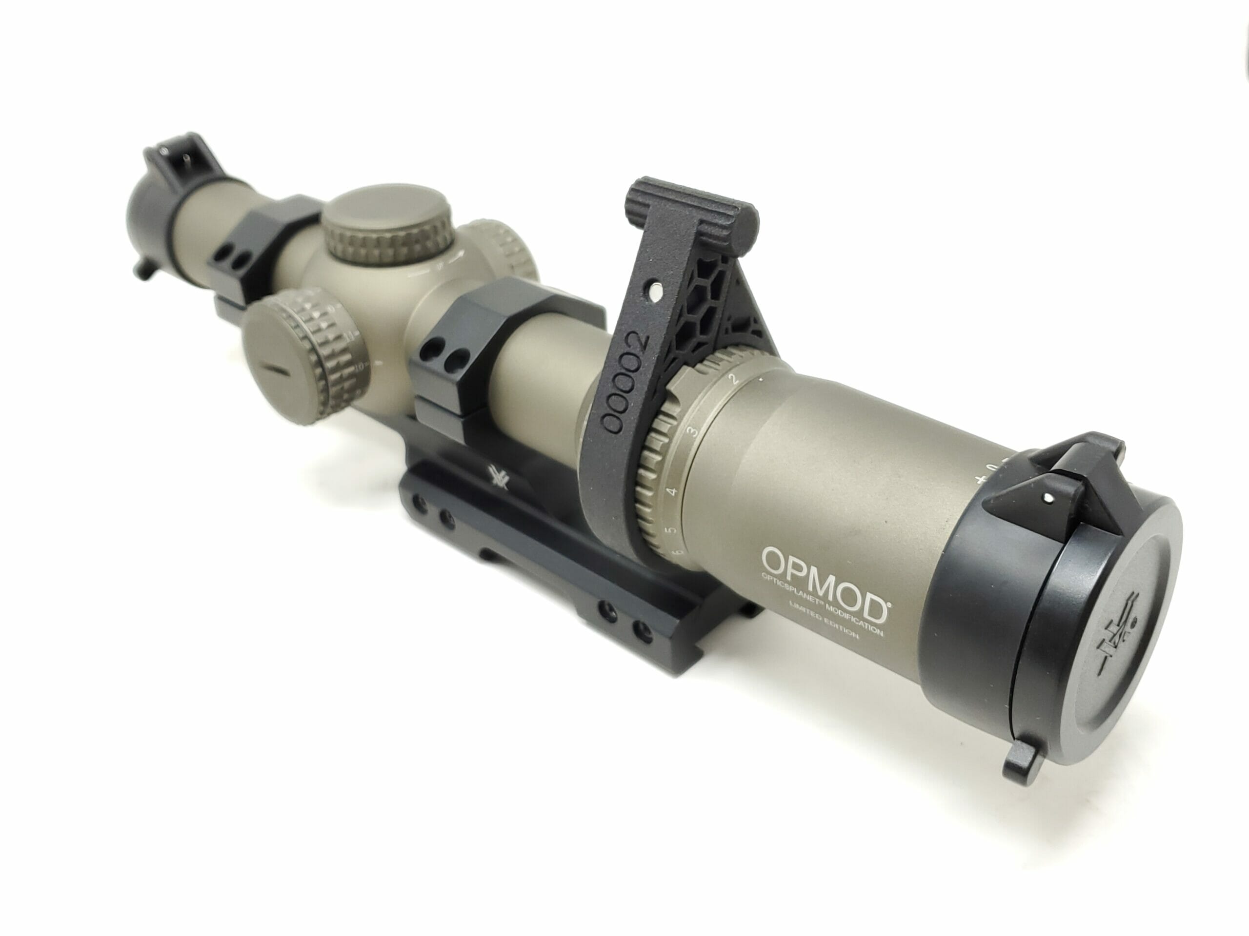
Optics mounts and accessories (throw levers and dust caps)
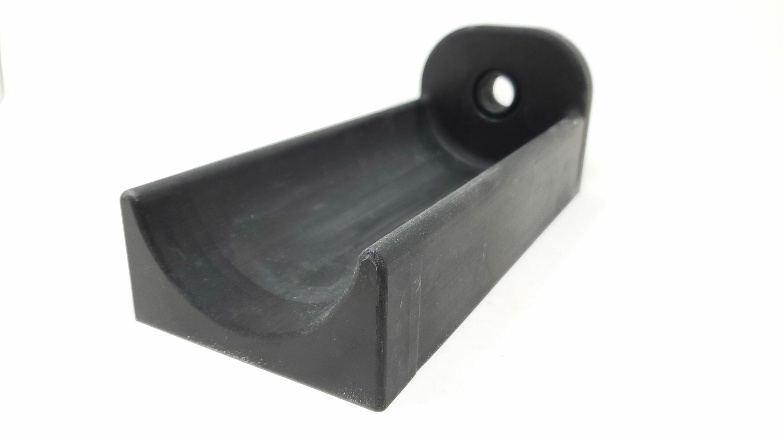
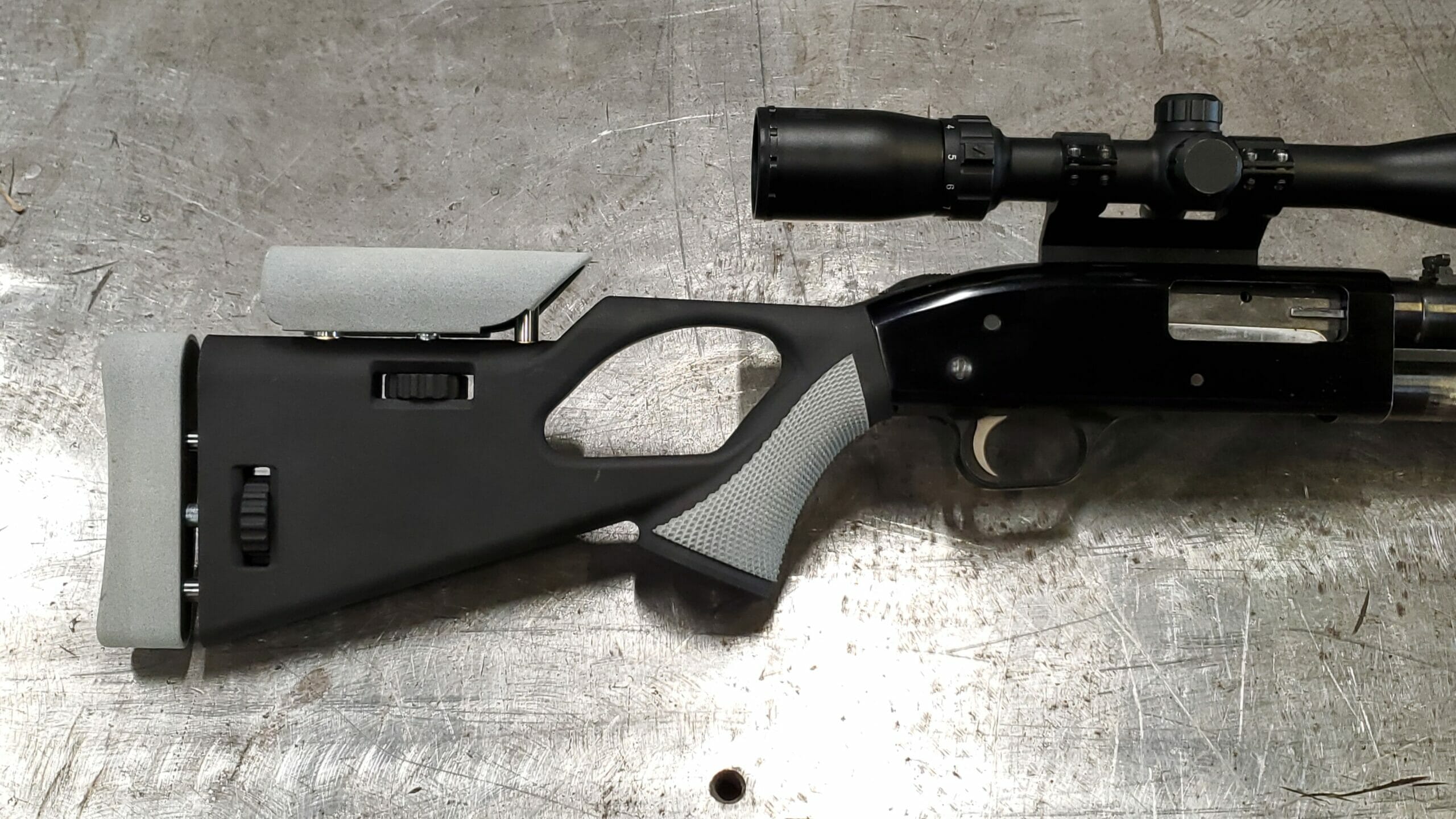
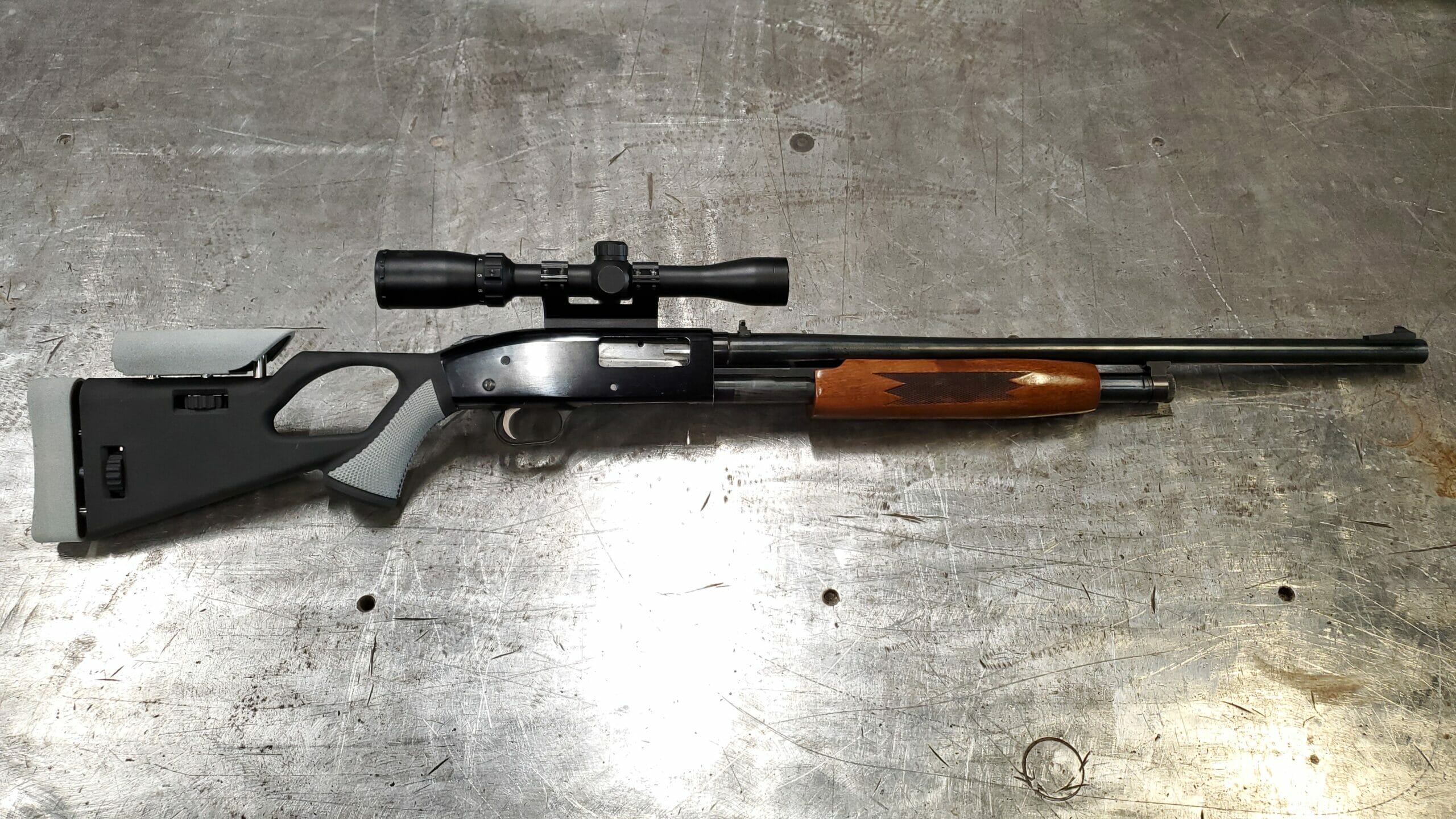
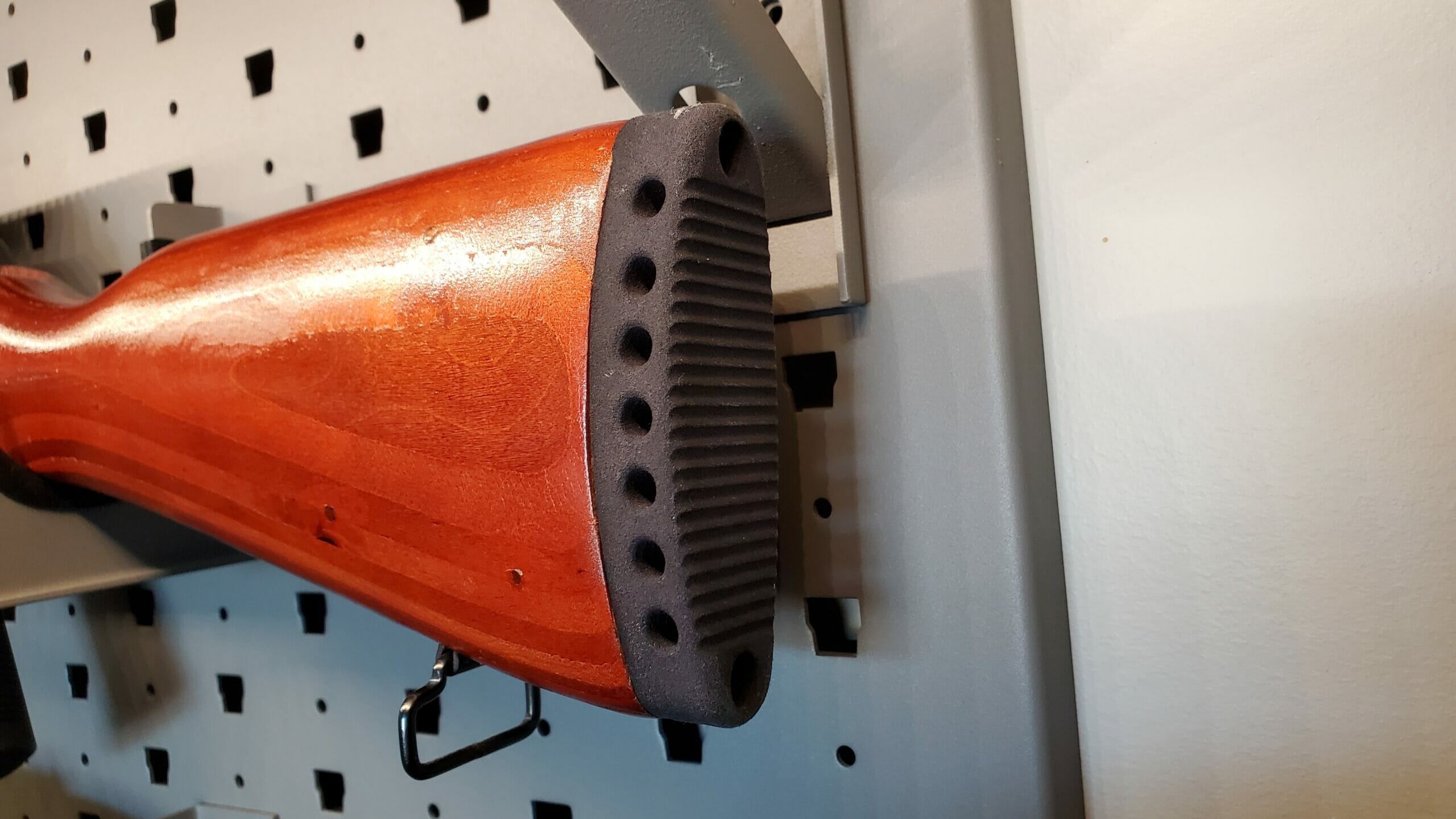
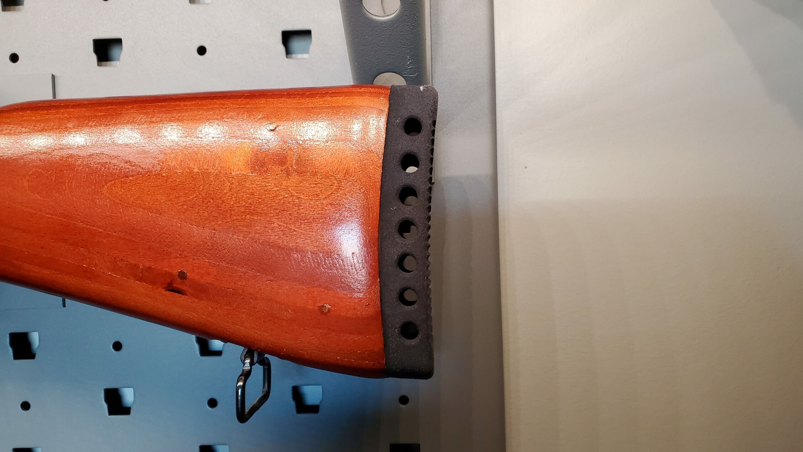
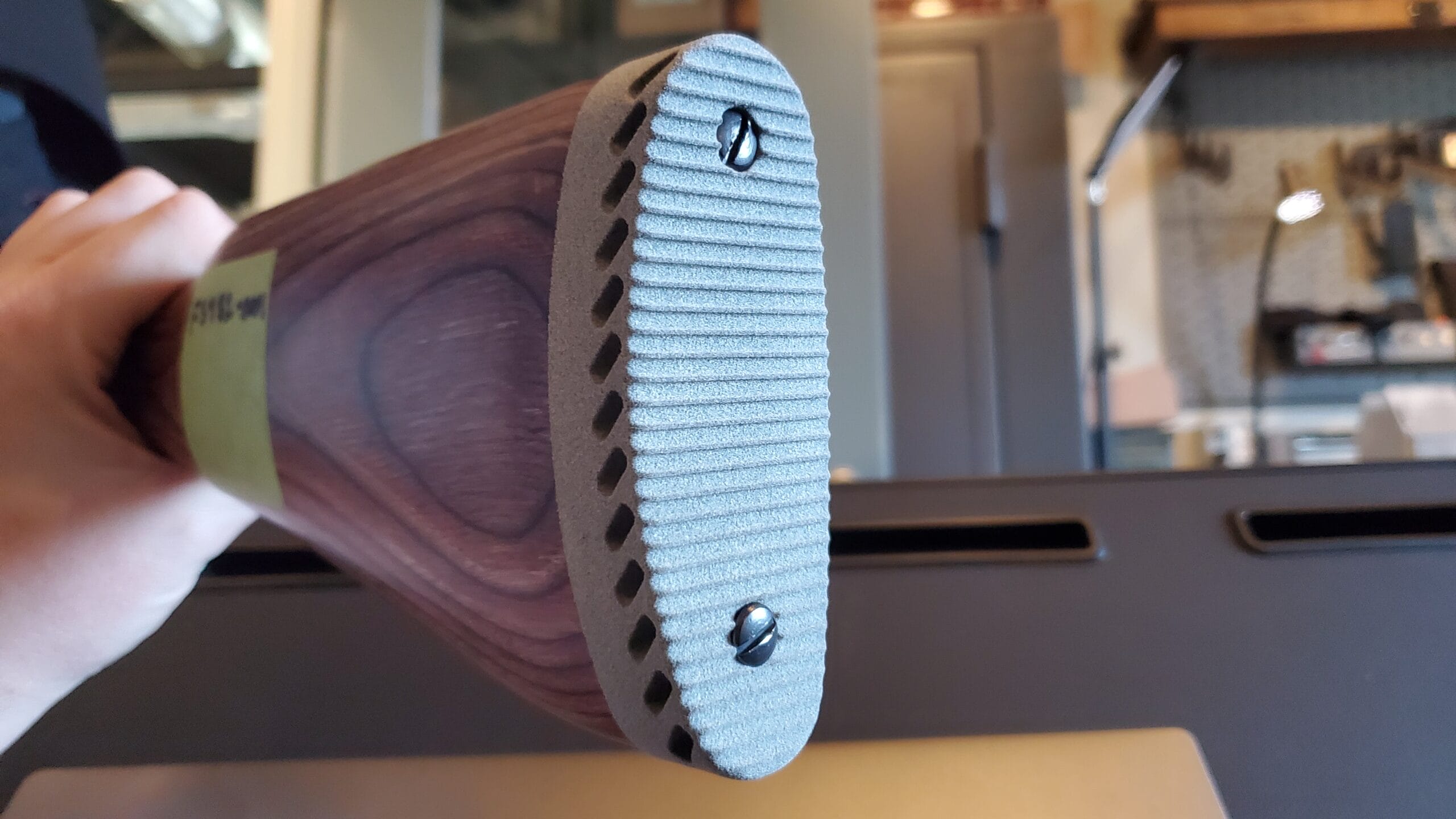
Rubber components like butt stock pads
Grips
Magazines (both prototype and production)
Accessory mounts
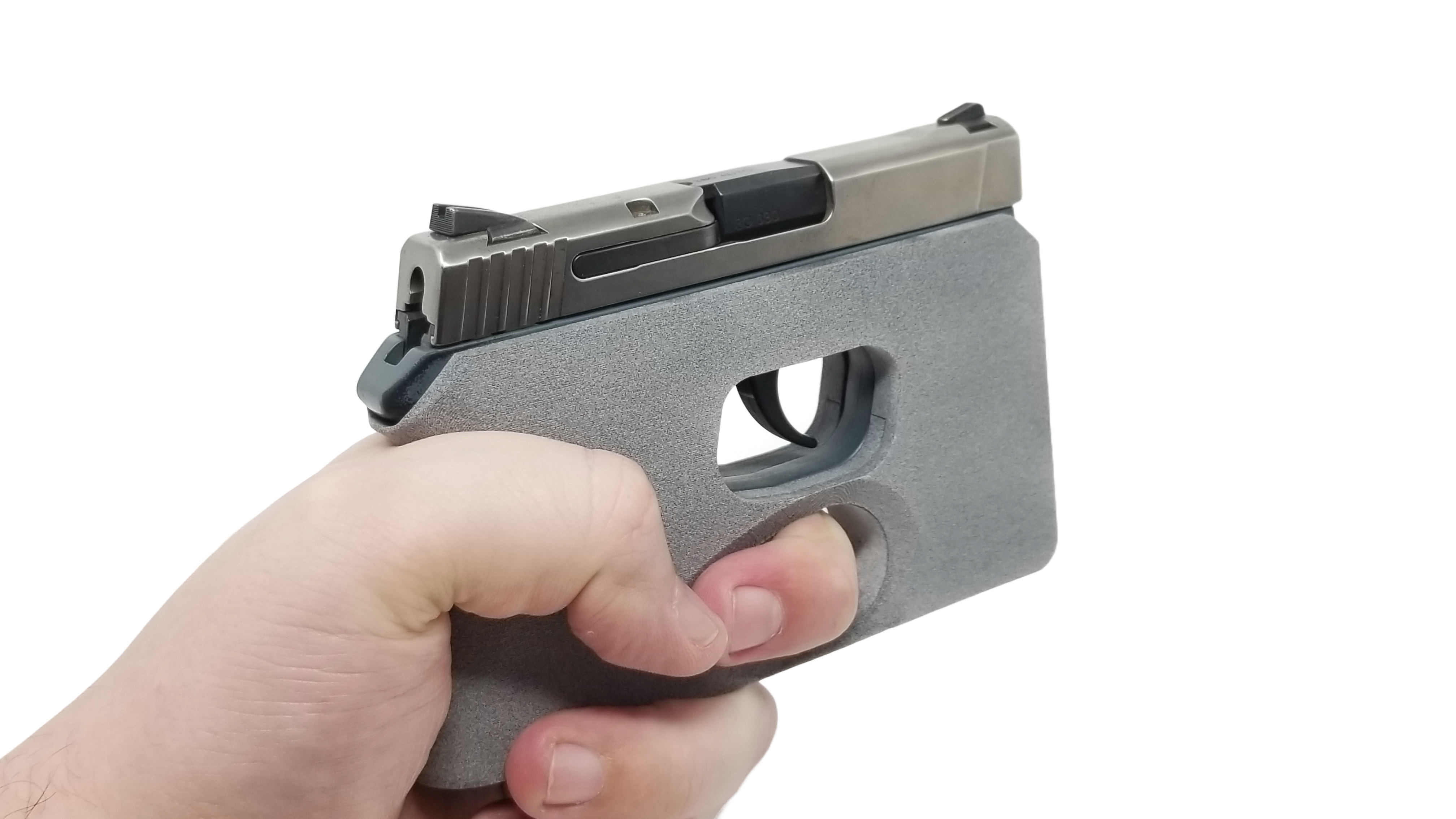
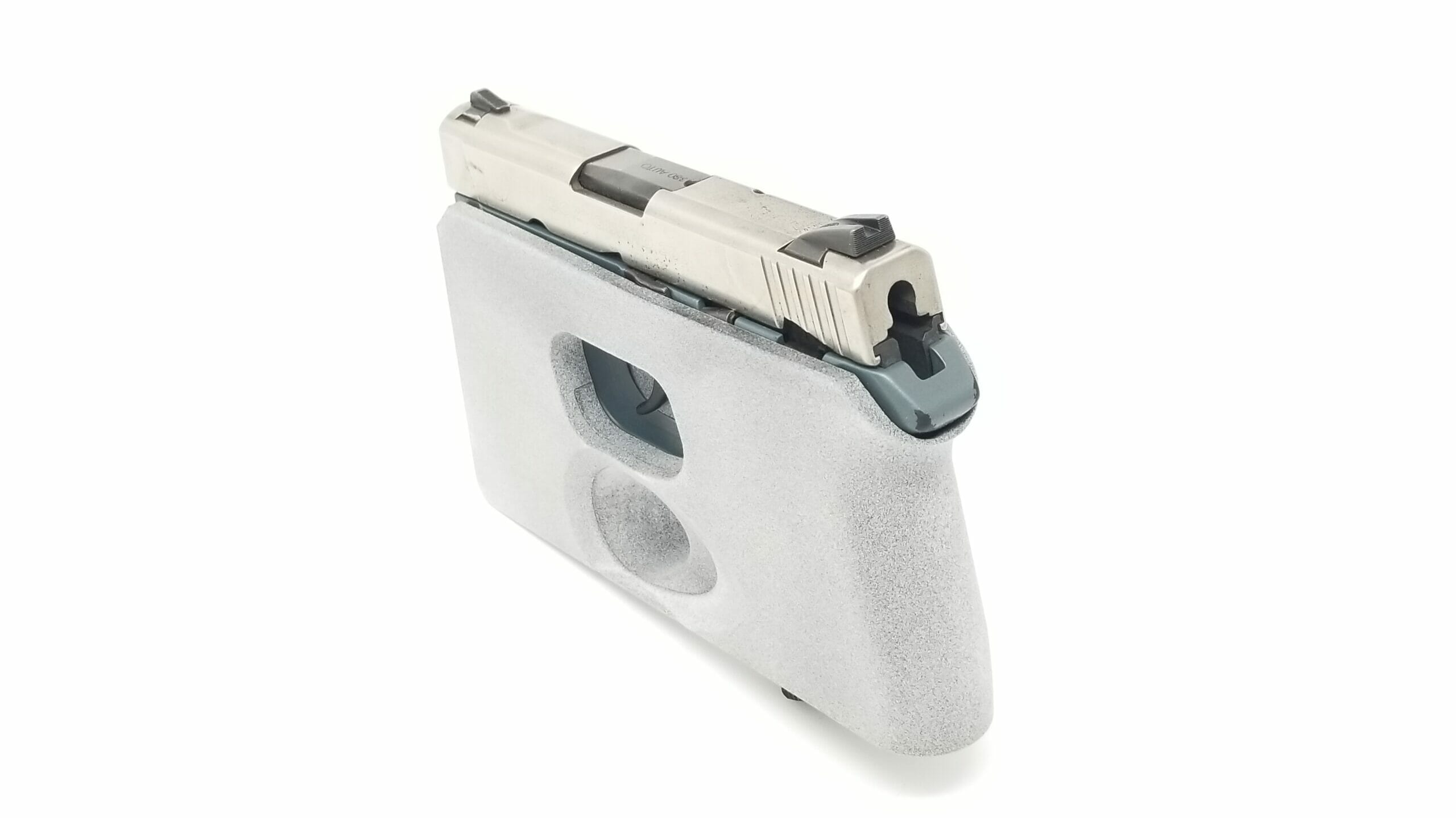
Holsters
Most of the 3D Printing projects we do for the Firearms Industry is done on our HP MJF Machines using materials like:
Nylon 12 (PA-12): Strong / wear resistant plastic, good for high temperature applications up to 350F
M95A TPU Rubber: Durable rubber that is 95A durometer and can be very stiff or flexible depending on part design.
With Forerunner 3D Printing having a Federal firearms License for Manufacturing (FFL 07), as well as a Special Occupational Taxpayer for Manufacturing (SOT 02) we can perform prototyping or contract manufacturing of your serialized or NFA firearm components in compliance with all ATF rules and regulations.
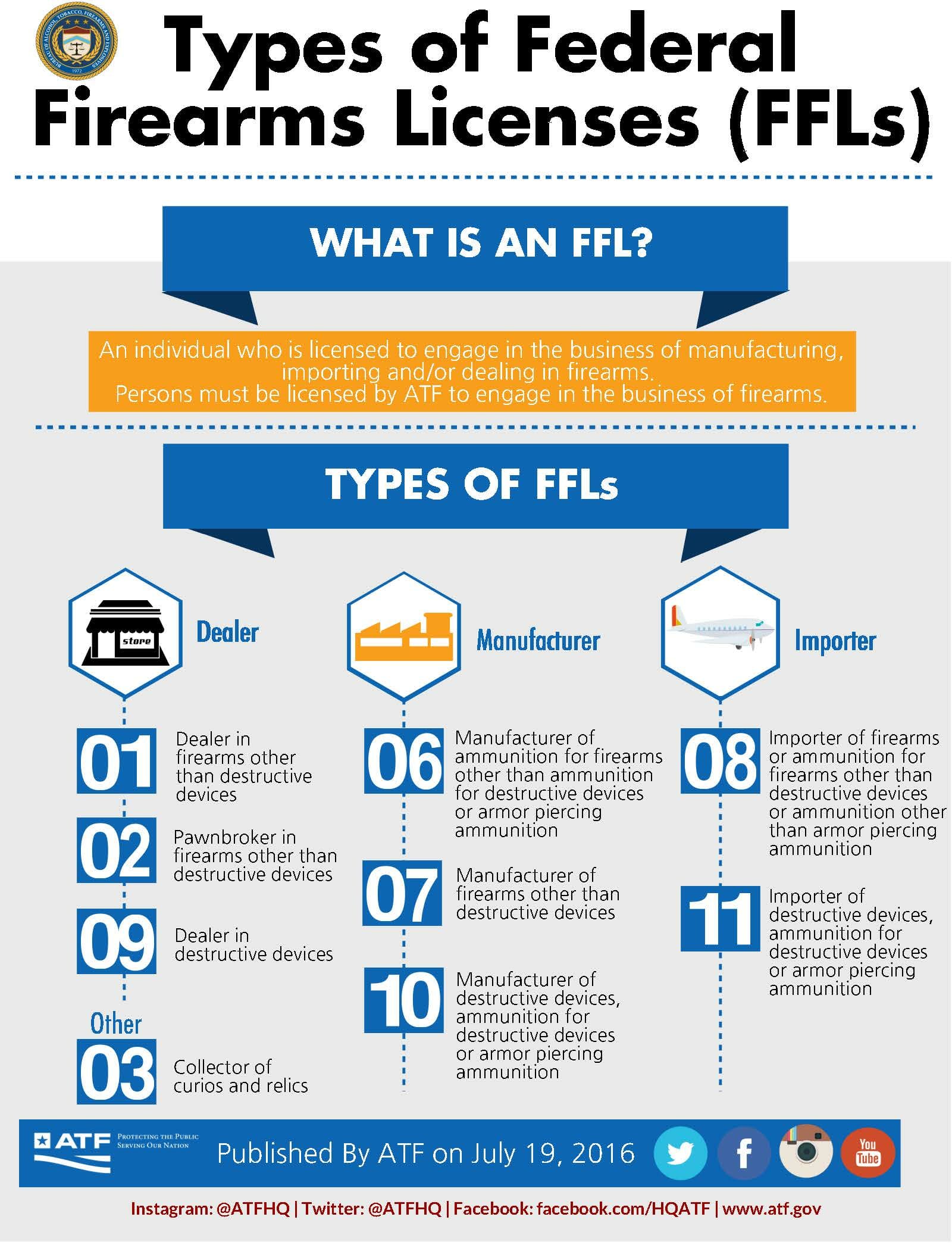
Federal Firearms License for Manufacturing (FFL 07)
There are multiple types of Federal Firearms Licenses each enabling the person or company holding them to transact in different areas of the firearms business. The chart you see to the right (click on it to view in full size) shows all the different types of FFL’s available and gives a summery of each.
At Forerunner 3DP we hold and FFL 07 which is a manufacturing FFL. This allows us to have customers ship their firearms directly to us for use on R&D projects, testing the fit up of prototypes, and for use as check fixtures during production runs. It also enables us to work as a contract manufacture making firearm parts for customers that are considered the registered (serialized) part of the fully assembled firearm. Without an FFL 07 it is impossible to manufacture any firearm part that requires a serial number to meet ATF requirements.
Special Occupational Taxpayer for Manufacturing (SOT 02)
Just like with the FFL system, there are various different classes of SOT as well, each allows the person or company that holds it the ability to transact in different parts of the National Firearms Act (NFA) business. At Forerunner 3D Printing we hold a SOT 02 which allows us to manufacture and serialize NFA firearms. These include:
Machine Guns:
Short-barreled shotguns (SBS) and Short-Barreled Rifles (SBR):
Suppressors:
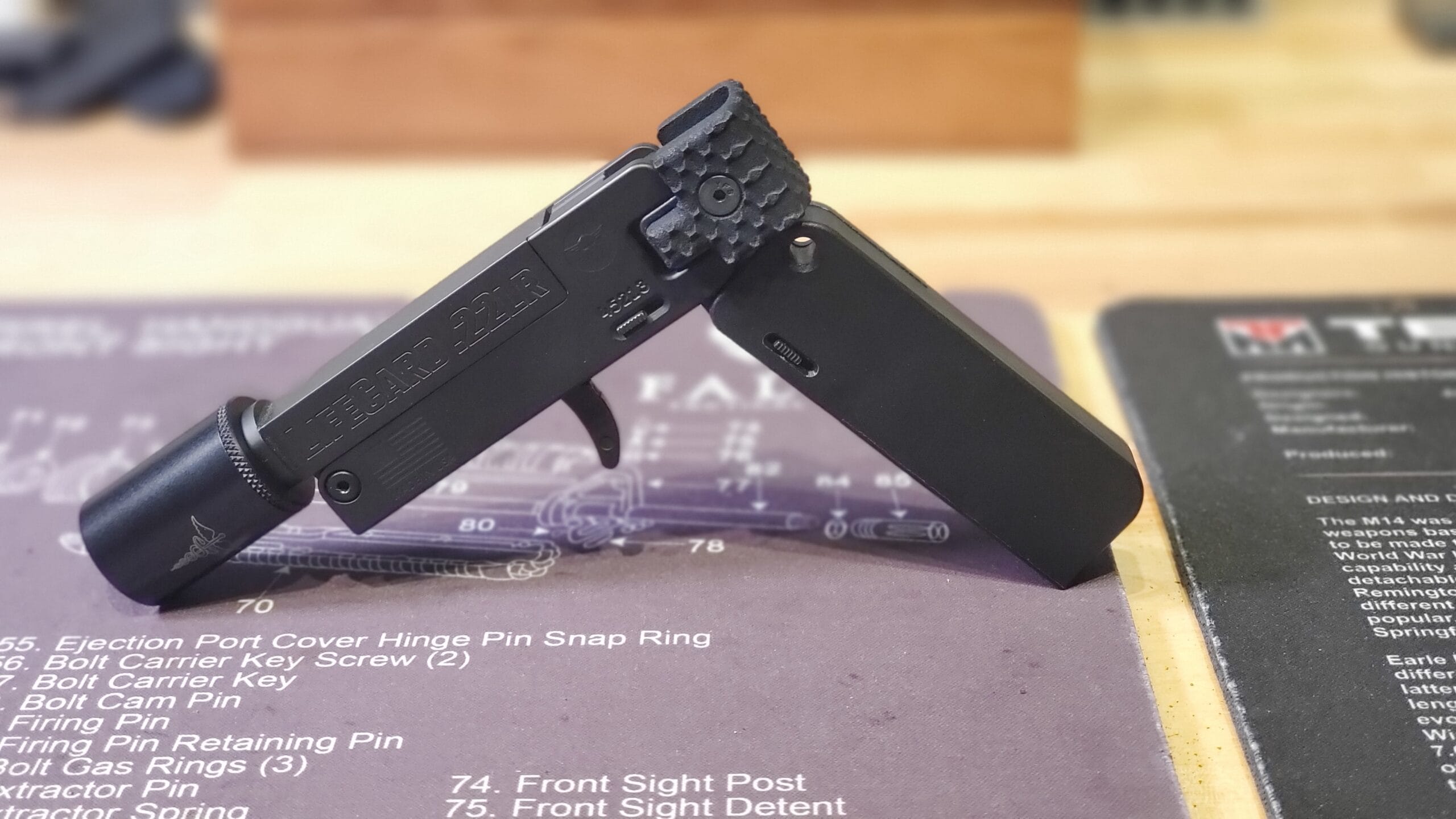
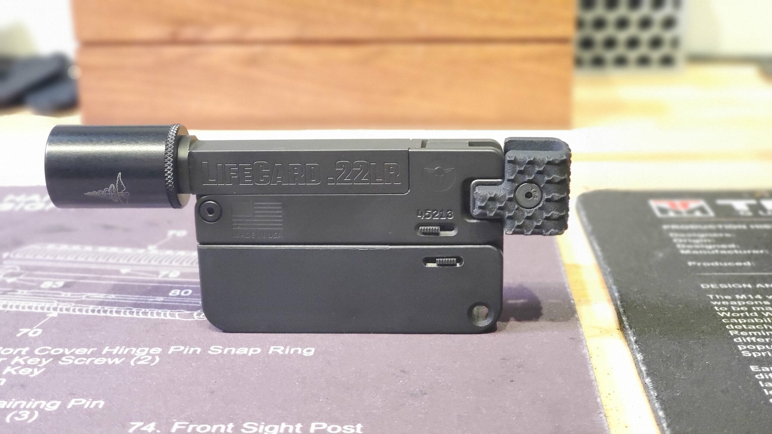
Any Other Weapon (AOW):
Device capable of being concealed on the person from which a shot can be discharged through the energy of an explosive
The History of 3D Printing in the Firearms Industry
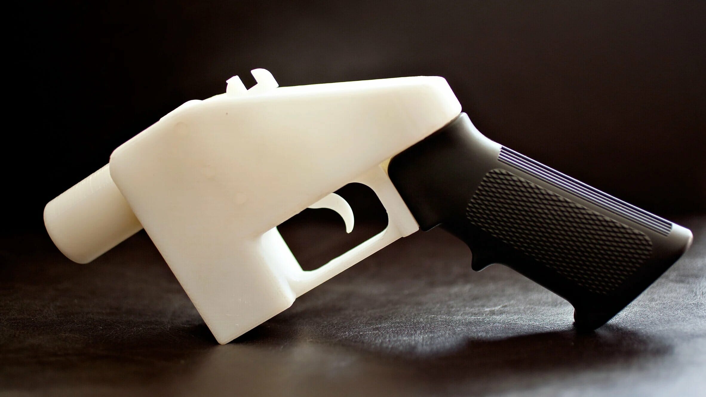
As 3D printing gained popularity in the early 2000s and desktop printers became more affordable, new possibilities opened for do-it-yourself enthusiasts. Private owners of the first 3D printing machines were able to access CAD files and print simple objects from a variety of plastics. Amid this new wave of 3D printed creations, the first models for firearms and firearm components in polymers began to pop up. However, it wasn’t until 2013 that the first fully functioning 3D printed gun, the notorious Liberator, made its appearance.
Liberator, first fully 3D printed firearm, also a notorious piece of crap and just as likely to blow up in your hand as actually fire.
The Liberator is a single-shot, polymer-based pistol created by Cody Wilson, founder of Defense Distributed. He published it on the company’s open-source file repository, DefCad, in May 2013. The gun’s publication came in reaction to Makerbot Industries removing firearm blueprints from its popular 3D model repository, Thingiverse in late 2012.
After only two days online, the US Department of State had the files pulled offline on the grounds of an infringement of the ITAR (International Traffic in Arms Regulations) – that the publishing of the files equated to an illicit export of firearms.
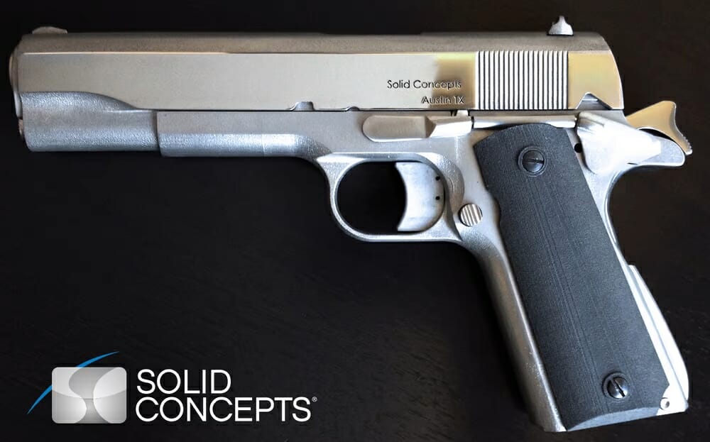
Solid Concepts 1911 DMLS, a real gun that was printed on a DMLS machine in Inconel and fitted and tuned by a gun smith. THIS is a real 3D printed firearm and blazed a path for the wide adoption of 3D printing for use in the firearms industry.
The same year that the Liberator ignited a fiery debate about 3D printed guns, additive manufacturing company Solid Concepts printed what’s thought to be the first industrially manufactured gun. Made from Inconel using the DMLS (Direct Metal Laser Sintering) printing process, the gun is called the 1911 DMLS and is a replica of the Colt Government Model 1911.
Forerunner 3D Printings entry into the world of 3D printed firearms
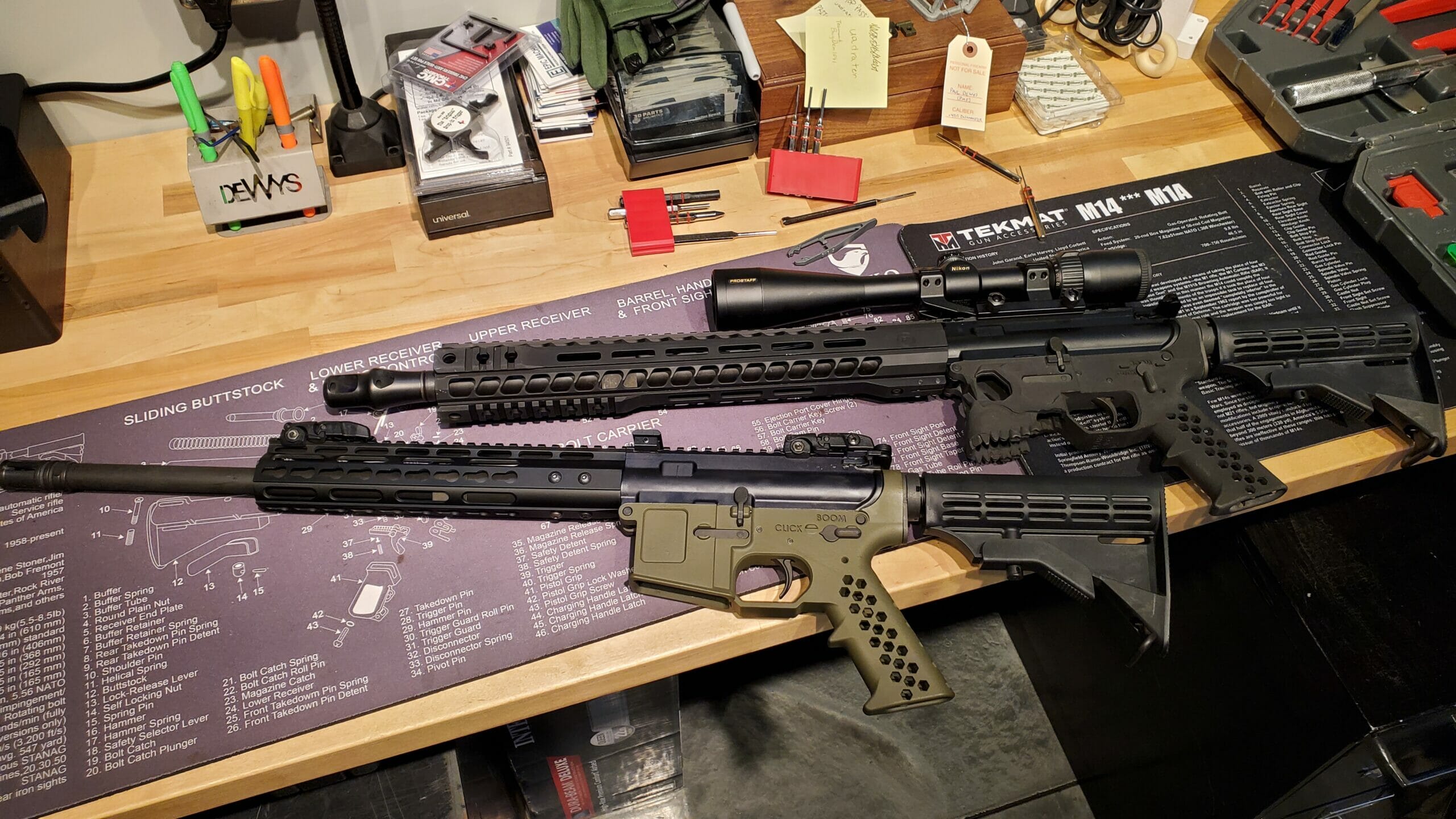
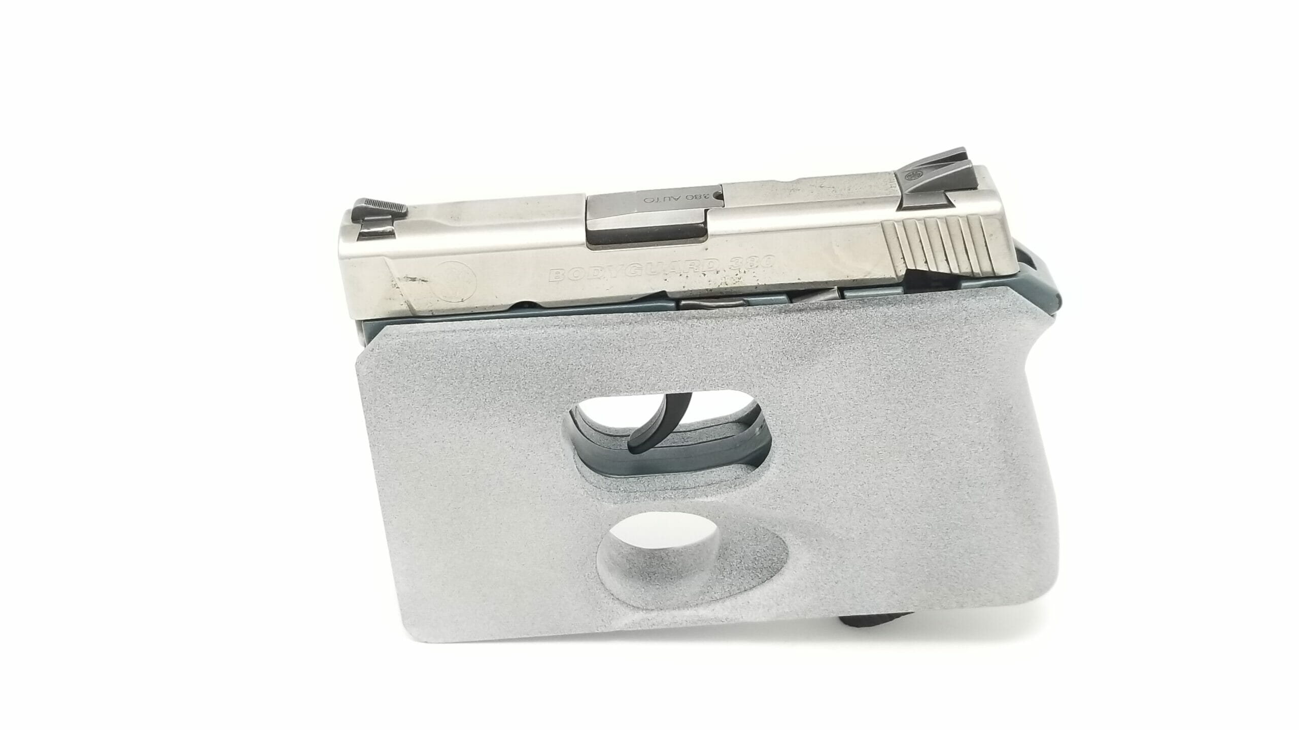
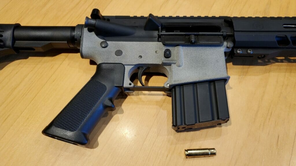
Fast forward to 2020 and Paul DeWys (owner of Forerunner 3D printing) set out to see if it would be possible to 3D print a homemade functional AR-15 lower receiver out of Nylon 12 on an MJF machine. He started with printing a mil spec lower and put it on a .300 AAC Blackout upper receiver. After 2000rds were fired through it without any issues it was time to take things to the next level and see if the lower would survive firing a larger caliber round.
First Mil Spec 3D Printed AR-15 lower paired up with an upper receiver chambered in .300 AAC Blackout.
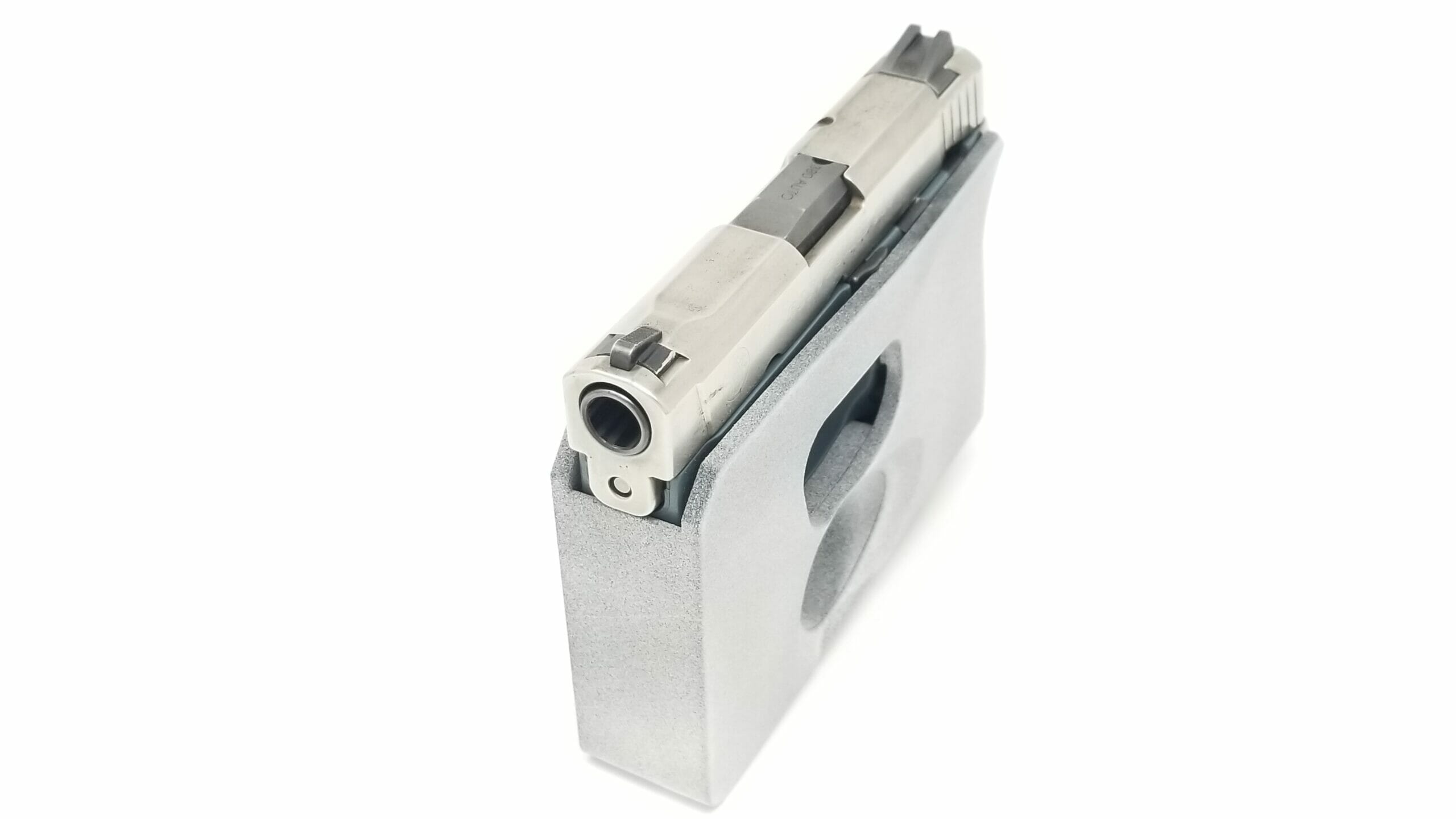
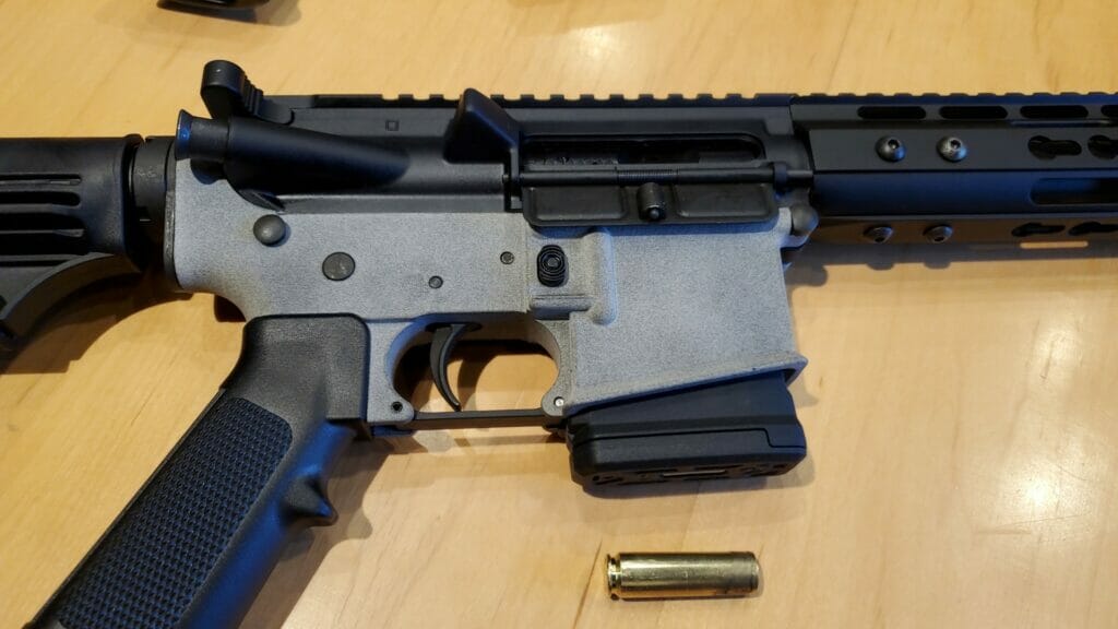
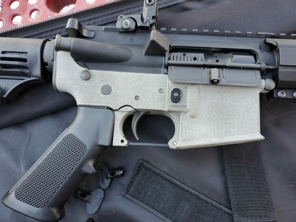
The mil spec lower was then paired up with an upper receiver chambered in .450 bushmaster, a MUCH larger cartridge. On test shot number 7 the lower broke at the connection point between the pistol grip and receiver. This was not entirely unexpected due to how thin the Nylon 12 material used to 3D print the lower got in this area.
First Mil Spec 3D Printed AR-15 lower paired up with an upper receiver chambered in .450 BushmasterFirst Mil Spec 3D Printed AR-15 lower after breaking on round #7 of .450 Bushmaster
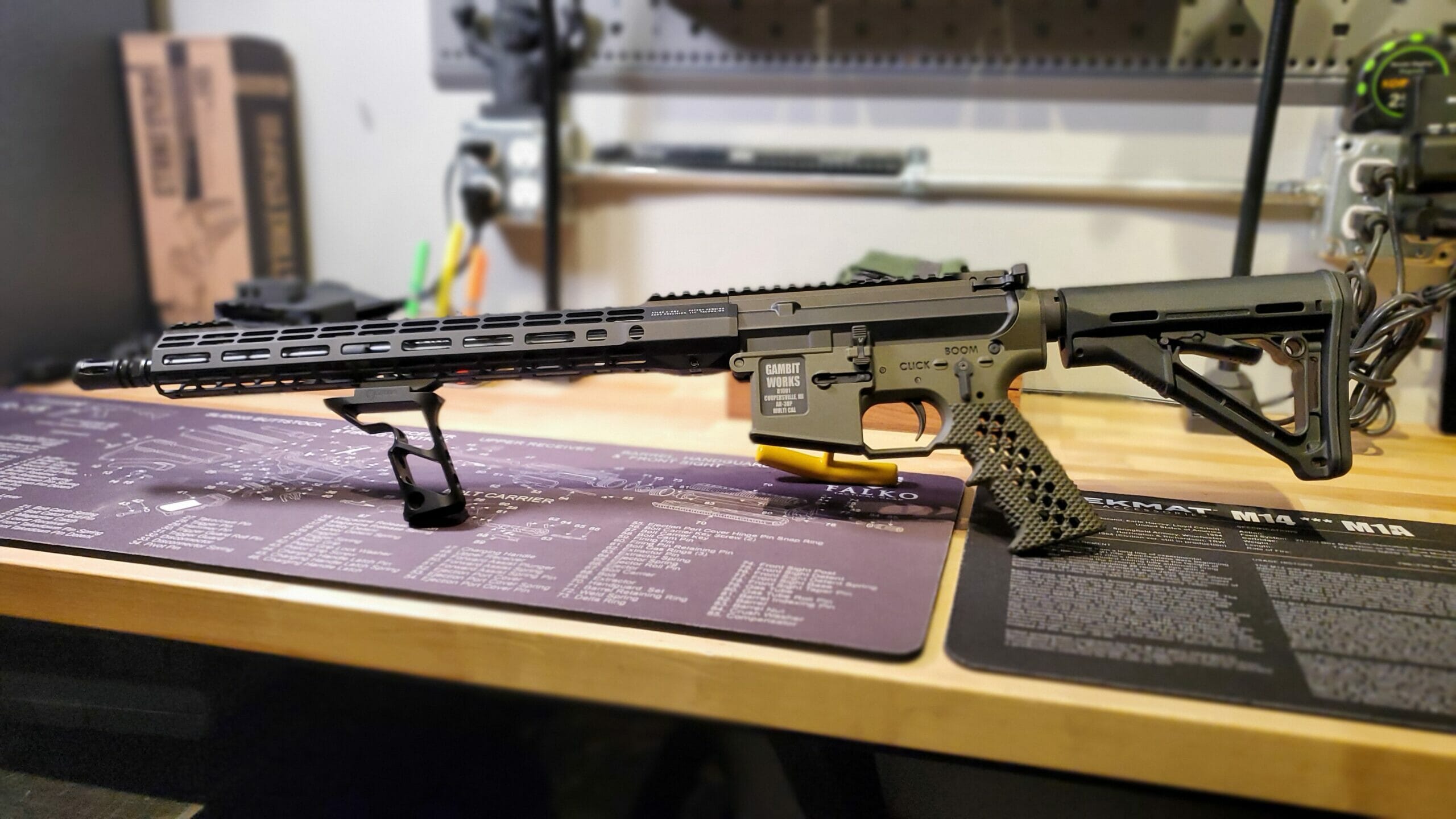
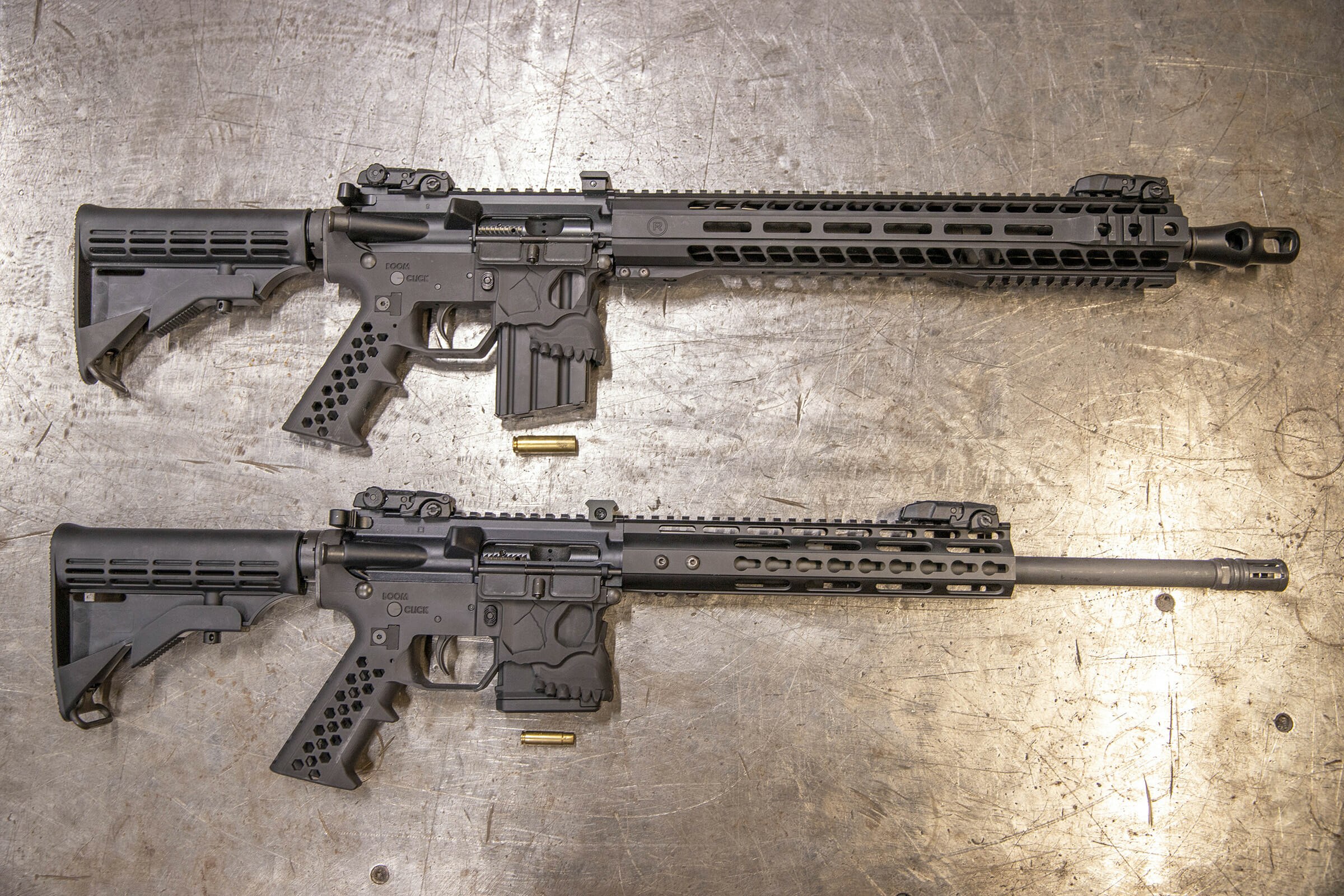
After some review of the design of the mil spec lower receiver and how it failed, a new design was made that integrated the pistol grip into the lower receiver which eliminated the failure point. This design passed extensive testing by Paul on the range using the .450 bushmaster round (Paul’s shoulder is still sore).
Redesigned 3D Printed AR-15 lower that has been strengthened to prevent failure when being used with large caliber rounds like the .450 bushmaster.Redesigned 3D Printed AR-15 lowers fully assembled and rocking a fresh coat of Armor Black Cerakote.
After these early experiments with using HP MJF Nylon 12 3D Printed lower receiver parts we found them to be not only viable, but quite impressive. At this point the team at Forerunner 3D Printing decided to start pursuing customer projects from the firearms industry. In September of 2022 F3DP pursued and was granted a Federal Firearms License for Manufacturing (FFL 07) in order to expand the range of prototype and production work we could take on from our firearms customers.