These guidelines are to be used as a starting point in understanding the basic aspects of part design and preparation for FDM components. When designing a part to be built using FDM technology, build process must be considered. FDM is accomplished by extruding thin layers of molten thermoplastic layer by layer until a part is produced, because FDM produces parts with specific characteristics and capabilities different from those of other prototyping processes, the systems have become increasingly used as a tool for producing manufactured products. This FDM Part Design Guide will be a valuable resource for evaluating and adjusting your designs to get this best results possible from this 3D Printing Technology.
FDM DESIGN CONSIDERATIONS – FDM Part Design Guide
The following information builds from conventional plastic part design to explain design considerations for manufacturing high-quality FUSED DEPOSITION MODELING (FDM) parts.
SHRINKAGE
Forerunner 3DP automatically adds shrink rates to the part when processed, so shrink factors do not have to be designed in. Default values can also be adjusted to fit specific geometries when large production runs of similar part designs are needed.
WARP
Since FDM systems add small amounts of molten material in a heated environment, warp is not a common problem. However, to avoid potential warping (deformation of vertical walls) when building thin-walled sections of a model, designers might select to add ribs to the walls (similar to what would be done with standard injection molding processes).
HOLES
Holes (those in bosses as well) on an FDM part are generally fractionally undersized. When tight tolerances are required, holes will be drilled or reamed to ensure the diameter is accurate.
COLUMNS AND PINS
Minimum pin or column size is a function of part orientation, tip size, and length. A Forerunner 3DP Sales Engineer can expand a column or pin to a minimum size based on the selected slice thickness. Custom groups can also be used to create smaller features down to 0.019 in. (0.48 mm).
WALL THICKNESS
Minimum wall thickness for FDM parts varies depending upon the slice thickness that will be used to build the part.
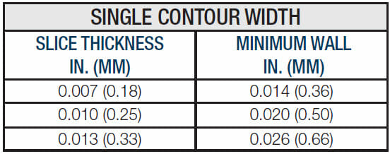
These wall thickness figures are a single contour width. Note: building multiple layers while using the minimum contour width will cause the feature to be brittle. (Note that warping may occur if there are large extents of minimum–thickness, vertical walls without support features like ribs or a support material tower.)
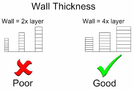
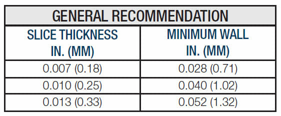
Forerunner 3DP encourages the use of the recommended minimum wall thickness (below), which will eliminate brittleness.
THREADS
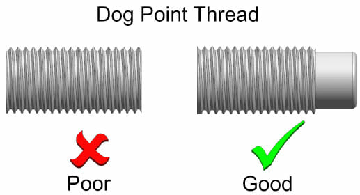
When designing built-in threads, avoid sharp edges and include a radius on the root. Sharp edges can be stress concentrators in plastic parts. Creating an ACME thread design with rounded roots and crests has been found to work well when using FDM. Also, use a “dog point” head of at least 1/32 in. (0.8 mm). This dog point design makes starting the thread much easier. Small threads produced from the FDM process are not recommended and not possible for holes or posts smaller than a 1/2″ diameter. An easy alternative is to use a tap or die to thread holes or posts.
UNDERCUTS
Because FDM is an additive process, undercuts for design features such as O-ring grooves are easily handled without causing manufacturing issues.
FILLETS
Although fillets are not necessary in FDM parts, they can be used to reduce stress concentrations and increase the overall strength of the part. Design fillets with an outer radius equal to the inner radius plus the wall thickness to maintain consistent thickness.

DRAFT ANGLE
Draft is unnecessary in FDM parts.
SIZE AND ORIENTATION
Forerunner 3DP can make single FDM parts as large as 36 in. x 24 in. x 36 in. (X, Y, and Z) (914 mm x 610 mm x 914 mm). Designers should note that extruded plastic has its strongest strength in the tensile mode along the x-y plane. Since the layers are held together by “hot flow” across the strands (one strand is cooling while the other is laid upon it), the lowest strength is in the Z-direction for both tensile and shear modes.
The Z-dimension brings another consideration to the FDM process. Overhanging non-supported features, such as the top of a closed box, require a foundation of support material to be built, which increases build time and material usage. Because of this, build orientation is usually determined by the part processor. For example, half of a box-shaped casing will be built with the main exterior facing down, so that no internal support is needed.
ASSEMBLIES
Proper clearance should be given between mating assembly parts to prevent them from fusing together. The standard guideline for creating clearances on assemblies being produced fully assembled is a minimum Z clearance of the slice thickness. The X/Y clearance is at least the default extrusion width based on a suggested minimum wall thickness. The minimum clearance needed for mating parts, when not producing the components fully assembled, is equal to the tolerance of the FDM machine itself.
GLUE JOINTS
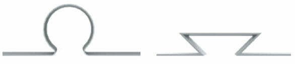
Parts larger than the maximum build size can be printed with the FDM process by splitting them into different parts. They can then be joined together by gluing. If you plan to glue parts together, you are recommended to include interlocking features such as those shown in the pictures below: as a guide to position the parts, to help them to bond together, and to facilitate the gluing process. Remember to leave an additional space of .004″ [0.1mm] – .008″ [0.2mm] between parts for the glue. At F3DP we utilize a specialized software called Magics that allows us to very easily and quickly split parts to make glue joints as needed. We offer this for free to our customers and can work with you to make sure you original design intent is maintained.
We recommend using Loctite HY4070 glue for assembling FDM parts. Here is a 3D Printing Glue Strength Guide.
SECTIONING PARTS
Parts may be sectioned (prior to manufacturing) in CAD, commercial rapid prototyping software applications, or by the Forerunner 3DP team. Sectioning can be used to:
- Build parts that are too big for the build chamber (cut parts into sections).
- Eliminate excessive amounts of support structure.
- Cut overhanging features from the top of the part (in its build orientation) and build separately.
- Preserve fragile features that may be damaged in post processing.
- Section fragile features from the part and build them separately. (Once fragile features are removed they can be built in an orientation that produces a stronger part. There are a number of bonding methods to reattach features and join sectioned parts.)
LIVING HINGE
Living hinges made from FDM materials can be used for a small number of cycles. If additional cycles are required consider using a different hinge design.
FASTENING HARDWARE
When using fastening hardware, Forerunner 3DP suggests designers use a cap screw or a flanged cap screw. The flat surface eliminates multidirectional stresses from cracking the part. Washers can also be used to spread the load over the largest possible surface area. Lock nuts, embedded nuts, or metal inserts are all stronger fastening options than adding threads to the FDM plastic.
BOSSES AND RIBS
Many times the design of FDM parts can be solid rather than using a hollowed out design supported by bosses and ribs. This can reduce build time and use less support material. It is not necessary to reduce wall thickness of a boss, rib, or gusset in FDM parts. Generally bosses can be the same size as the part thickness or up to 0.02 in. (0.5 mm) less. It is also important to use gussets or ribs to support the bosses in FDM parts. This will increase the amount of stress the feature can withstand.
TEXT
Minimum suggested text size on the top or bottom build plane of a FUSED DEPOSITION MODELING (FDM) model is 16 point boldface. Minimum suggested text size on vertical walls is 10 point bold. In most cases the supports generated to support text on a vertical wall can be eliminated to save time and material.
FINISHING & SECONDARY OPERATIONS
Since the FUSED DEPOSITION MODELING (FDM) process uses engineering-grade thermoplastics, the parts produced are capable of withstanding a number of post-manufacturing processes, including machining operations such as drilling and tapping, sawing, turning, and milling. (Note that heat is easily built up in plastic parts, so removing the material slowly and using coolant keeps the part from distorting.) Other post processing operations may include smoothing, burnishing, sealing, joining, bonding, and plating.