Testing Summary
MJF printed PA12 parts have proven to be watertight without any additional post-process (unlike SLS parts that must be chemically sealed after printing). Therefore, MJF printed parts can be used as manifolds or pipelines that work with fluids, even under pressure. The purpose of this article is to document the experiments used for testing HP MJF 3D Printed Pressure Vessels and results that were discovered.
These are the main variables of design which define the maximum pressure any given part can withstand:
- Wall thickness
- Shape
- Temperature
- Type of fluid
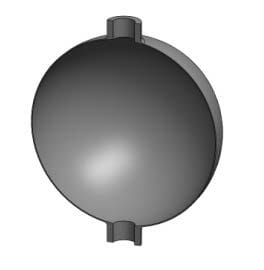
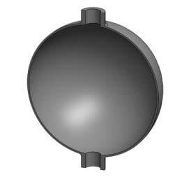
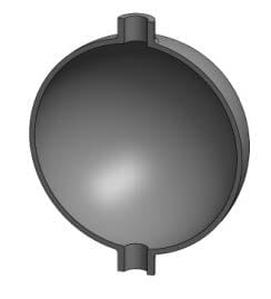
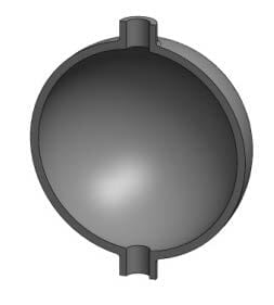
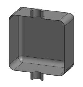
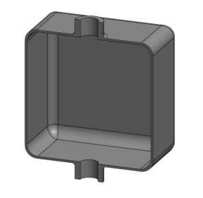
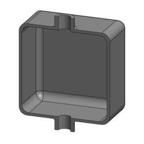
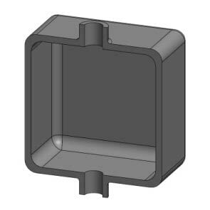
The types of geometries that were selected for testing in order to simulate fluid ducts and containers under pressure. Each part has a volume of 30.5 Cubic Inches.
Wall thickness 43 PSI 145 PSI 290 PSI .05" Recommended Not recommended Not recommended .1" Recommended Recommended Not recommended .157" Not recommended Recommended Recommended Vessel shape Spherical Recommended Recommended Recommended Cylindrical Recommended Recommended Recommended Cubic Not recommended Break Break
The best shape to work with fluids under pressure is a sphere, because the pressure is better distributed and there are no flat surfaces, which will deform and break easier. Therefore, it is recommended to design fluid vessels as close to a spherical shape as possible, because this will help to withstand higher pressures.
Thanks to the water tightness of the HP High Reusability PA12, the printed parts have the following advantages when they are used as fluid vessels replacing other traditional technologies:
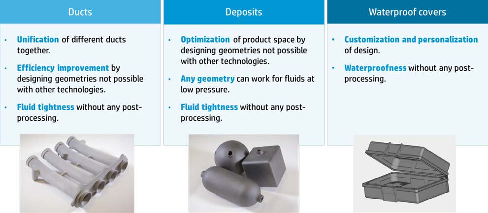
HP MJF 3D Printed Pressure Vessel Testing – Leakage test results
The leakage test has been done to determine the possibility of leaks and pressure losses of MJF parts working with a fluid under pressure. The water is introduced into the different test specimens at a specific pressure and is left for a period of 7 hours. During that time, the specimens are checked to detect any pressure loss that could appear due to material deformation or leakage.
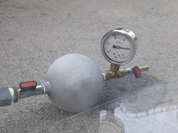
Wall thickness analysis
The water tightness characterization test has been done using 3 different wall thicknesses. These have been selected due to their wide use in fluid-vessel components: .05″ (1.25mm) , .1″ (2.5mm) and .157″ (4mm).
The behavior of the parts with different wall thicknesses under different pressures will identify the best wall thickness depending on the circumstance. From the test results, the recommended values obtained are:
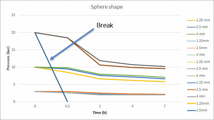
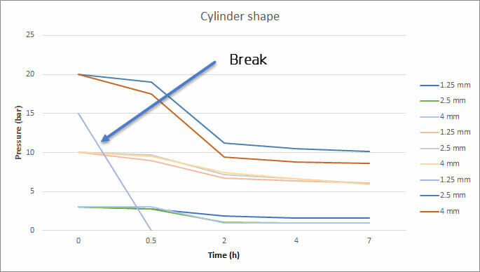
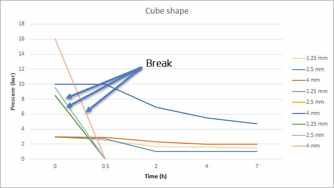
HP MJF 3D Printed Pressure Vessel Testing – Breakage test results
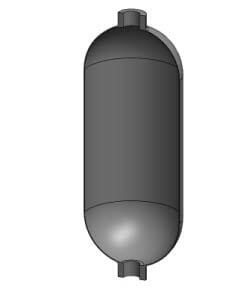
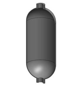
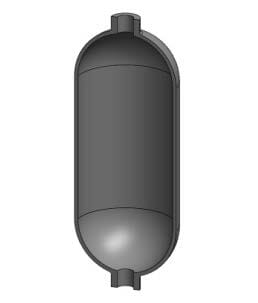
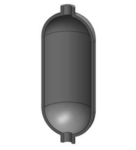
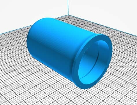
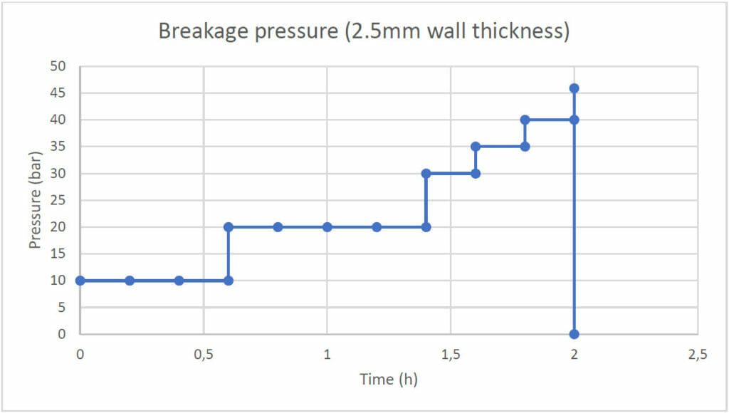
The breakage test measures what the maximum pressure a sample can withstand before it breaks is. This test was done with a part (shown below) with a .1″ (2.5mm) thick wall:
Comparison against other technologies
The breakage test has been also done with other materials in order to benchmark the performance of MJF printed parts compared to competitors. MJF parts can withstand similar pressures to SLS, and higher than other technologies, such as SLA or Material Jetting.
Machine Technology Material Temperature Broken At Objet Connex500 Material Jetting Photopolymer Vero Clear 86F 580 PSI Projet 3500 Max Material Jetting VisiJet (Crystal) SR200 86F 435 PSI Projet 6000 SLA VisiJet Tough 86F 362 PSI Projet 6000 SLA VisiJet Hi-Temp 140F 435 PSI EOS Formiga P100 SLS PA2200 86F 652 PSI HP Jet Fusion 4200 MJF PA12 86F 652 PSI
Pressure resistance (wall thickness .1" / 2.5 mm)