How does SLS 3D Printing work:
Selective laser sintering (SLS) was developed and patented by Dr. Carl Deckard and Dr. Joe Beaman at the University of Texas at Austin in the mid-1980s. Deckard and Beaman were involved in the resulting start up company DTM, established to design and build the SLS machines. In 2001, 3D Systems, the biggest competitor to DTM and SLS technology, acquired DTM. This page discusses in detail the advantages of using SLS technology to 3D print parts. It explains the most common SLS materials, offers rules for designers to follow when printing with SLS, and also shows a gallery of various parts that were produced using SLS 3D Printing equipment.
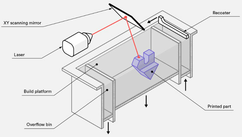
Selective laser sintering (SLS) is an additive manufacturing (AM) technique that uses a laser as the power and heat source to sinter a powdered material (typically nylon or other plastic). At the start of a new layer the print bed is dropped by 0.004”- 0.006” depending on the material being printed. The recoater picks up a load of freshly heated raw powder from the material storage bin and moves across the build platform filling in the thickness that the build platform has been dropped with the fresh hot powder. At this point the laser comes on and begins tracing and hatching that slice of the parts being printed. The part slice is defined by a 3D model that has been loaded into the machines build management software. As the laser sweeps across the areas being sintered it is binding the material together to create a solid structure. After the powder is sintered, the parts must be allowed time to cool. Depending on the size of the parts, cooling time usually takes equally as long as the time it took to print the job in the first place. For that reason SLS jobs usually have longer lead times (at least 1 day for production and 1 day for cooling) when compared to other printing technology like SLA, PolyJet, or FDM. For extremely large SLS parts (something larger than 20″ x 20″ X 10″), printing can span several days followed by several days of cool down time.
Selective Laser Sintering uses high-powered lasers to sinter powdered material, binding it together to create a solid structure. This printing process is considered to be a support free process. The parts are supported by unsintered powder that is left over after that layer has been sintered. Once the printing of that build is complete, the part(s) are removed from the block of loose unsintered powder they are trapped inside of and cleaned by hand and using air jets and a bead blaster to remove all the excess powder that is still clinging to the surface of the part.
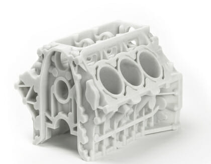
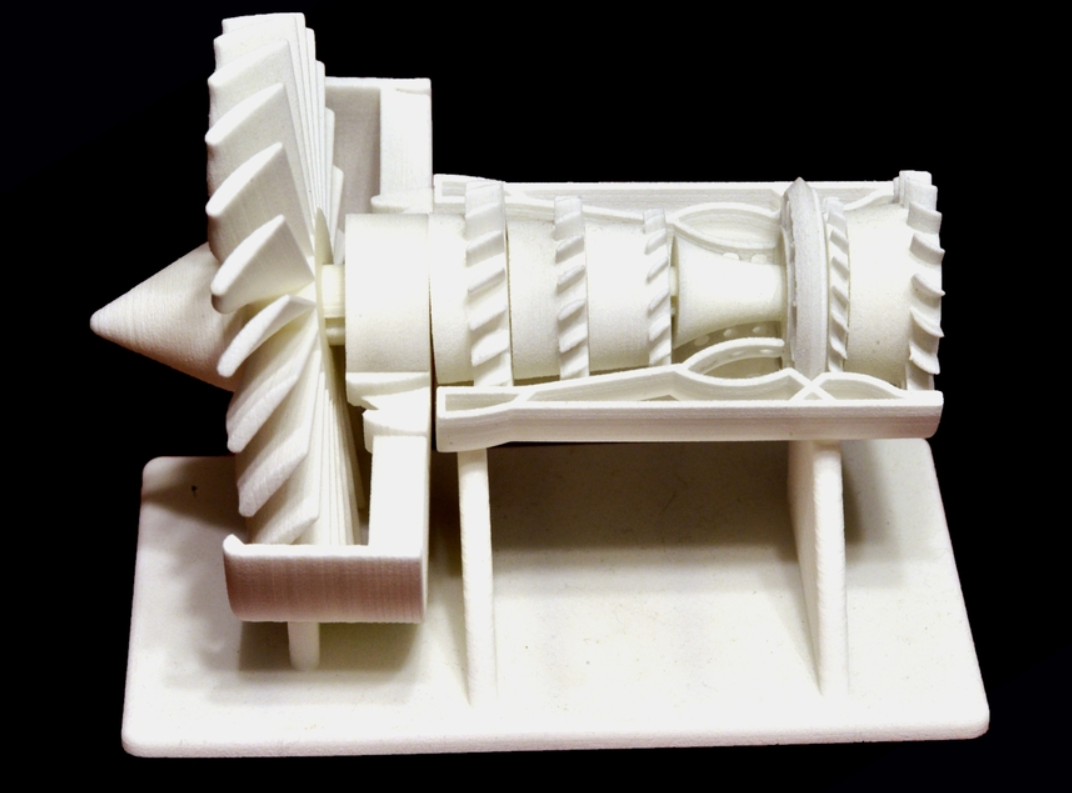
SLS is known for having a relatively good level of accuracy, cheap raw material costs, the ability to easily make complex geometries without supports, parts that are very strong, and producing parts that can handle high temperatures (300F+). This makes it an incredibly useful technology for a broad range of applications in things like prototype parts, investment casting patterns, automotive parts, and wind tunnel models. It is also commonly used for low volume manufacturing of end use parts for aerospace, military, medical, pharmaceutical, and electronics hardware. On a shop floor, SLS can be used for rapid manufacturing of tooling, nesting, and fixtures.
Common applications for SLS parts:
- Engine compartment applications (high temperature)
- Ducts
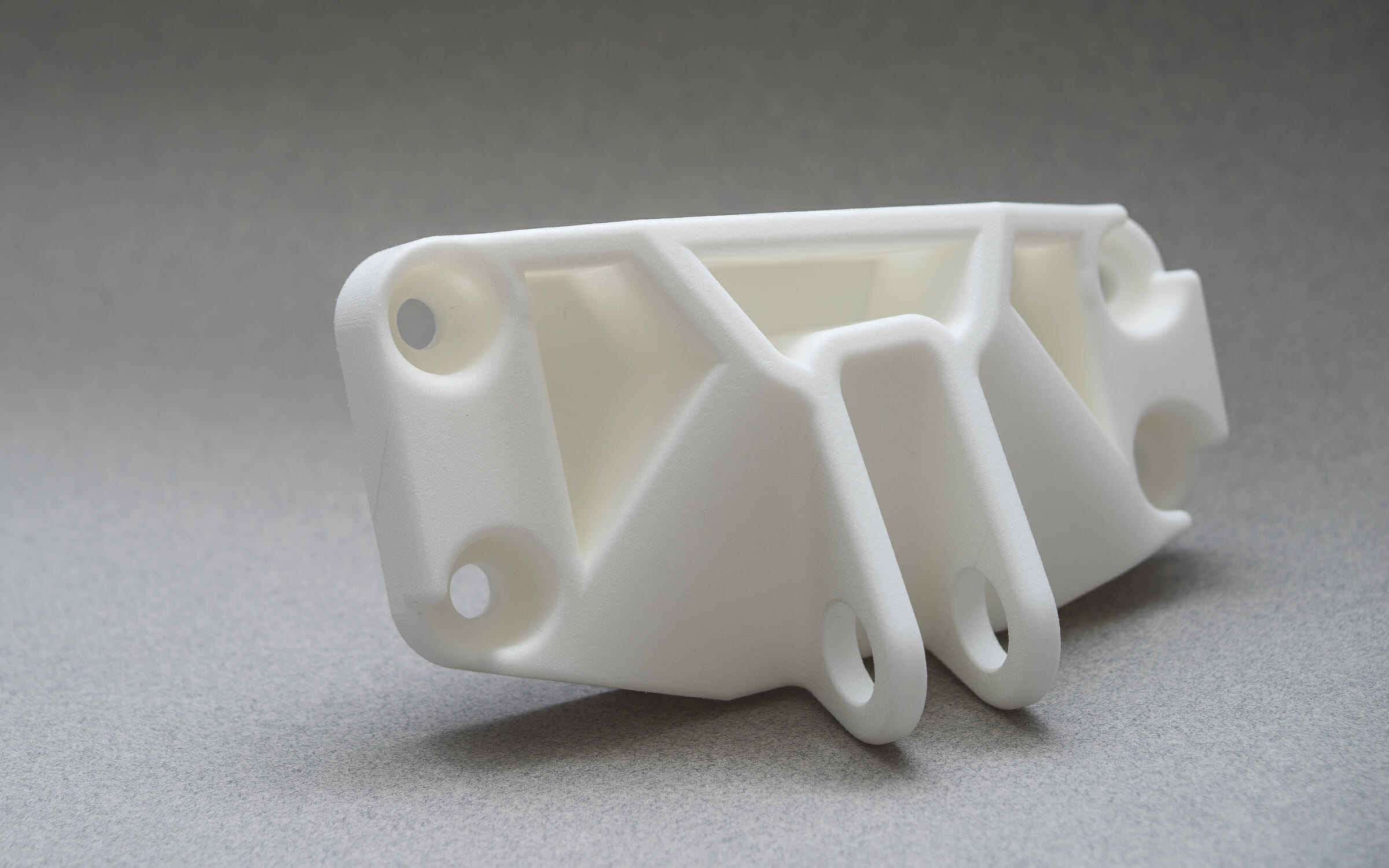
- Housings
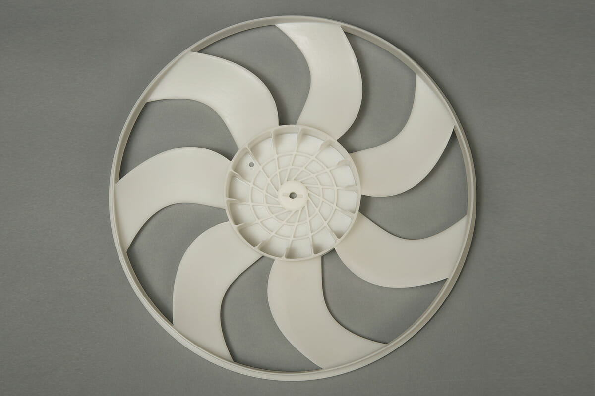
- Impellers
- Tanks / bottles
- Living hinges
SLS 3D Printing Materials:
PA 2200 (PA-12): White polyamide 12 powder with a well-balanced property profile and a wide variety of applications it can be used forLaser-sintered parts made from PA 2200 possess excellent material properties:
- Color: White
- High strength and stiffness
- Good chemical resistance
- Excellent long-term environmental behaviour
- High detail resolution on printed parts
- Various finishing options available
- Bio compatible according to EN ISO 10993-1 and USP/level VI/121 °C
Typical applications of this material are things like high quality fully functional plastic parts. Due to the excellent mechanical properties of this material it is often used as a substitute for Nylon injection moulding plastics. The biocompatibility of this material allows for its use on prostheses and the high abrasion resistance it possesses allows for part with movable connections.
| Mechanical properties | Value / Unit | Test Standard |
| Flexural Modulus, 23°C | 1500 MPa | ISO 178 |
| Flexural Strength | 58 MPa | ISO 178 |
| Izod Impact notched, 23°C | 4.4 kJ/m² | ISO 180/1A |
| Izod Impact unnotched, 23°C | 32.8 kJ/m² | ISO 180/1U |
| Shore D hardness (15s) | 75 | ISO 868 |
| Ball indentation hardness | 78 MPa | ISO 2039-1 |
| 3D Data | Value / Unit | Test Standard |
| Tensile Modulus (X Direction) | 1700 MPa | ISO 527-1/-2 |
| Tensile Modulus (Y Direction) | 1700 MPa | ISO 527-1/-2 |
| Tensile Modulus (Z Direction) | 1650 MPa | ISO 527-1/-2 |
| Tensile Strength (X Direction) | 48 MPa | ISO 527-1/-2 |
| Tensile Strength (Y Direction) | 48 MPa | ISO 527-1/-2 |
| Tensile Strength (Z Direction) | 47 MPa | ISO 527-1/-2 |
| Strain at Break (X Direction) | 24 % | ISO 527-1/-2 |
| Charpy impact strength (+23°C, X Direction) | 53 kJ/m² | ISO 179/1eU |
| Charpy notched impact strength (+23°C, X Direction) | 4.8 kJ/m² | ISO 179/1eU |
| Thermal Conductivity (X Direction) | 0.144 W/(m K) | DIN 52616 |
| Thermal Conductivity (Y Direction) | 0.144 W/(m K) | DIN 52616 |
| Thermal Conductivity (Z Direction) | 0.127 W/(m K) | DIN 52616 |
| Thermal properties | Value / Unit | Test Standard |
| Melting temperature (10°C/min) | 176 °C | ISO 11357-1/-3 |
| Vicat softening temperature A | 181 °C | ISO 306 |
| Vicat softening temperature (50°C/h 50N) | 163 °C | ISO 306 |
More info on this material / full material spec sheet
PA 3200 GF is a whitish, glass-filled polyamide 12 powder, which is characterised by an excellent stiffness in combination with good elongation at break. Laser-sintered parts made from PA 3200 GF possess excellent material properties:
- Color: White
- High stiffness
- High mechanical wear-resistance
- Good thermal loadability
- Excellent surface quality
- High dimensional accuracy and detail resolution
- Good processability
- Excellent long-term constant behaviour
A typical application for PA 3200 GF is for end use parts within the engine bay of cars, for deep-drawing dies or any other application which requires particular stiffness, high heat distortion temperature and low abrasive wear.
| Mechanical properties | Value / Unit | Test Standard |
| Izod Impact notched, 23°C | 4.2 kJ/m² | ISO 180/1A |
| Izod Impact unnotched, 23°C | 21 kJ/m² | ISO 180/1U |
| Shore D hardness (15s) | 80 | ISO 7619-1 |
| Ball indentation hardness | 98 MPa | ISO 2039-1 |
| 3D Data | Value / Unit | Test Standard |
| Tensile Modulus (X Direction) | 3200 MPa | ISO 527-1/-2 |
| Tensile Modulus (Y Direction) | 3200 MPa | ISO 527-1/-2 |
| Tensile Modulus (Z Direction) | 2500 MPa | ISO 527-1/-2 |
| Tensile Strength (X Direction) | 51 MPa | ISO 527-1/-2 |
| Tensile Strength (Y Direction) | 51 MPa | ISO 527-1/-2 |
| Tensile Strength (Z Direction) | 47 MPa | ISO 527-1/-2 |
| Strain at Break (X Direction) | 9 % | ISO 527-1/-2 |
| Strain at Break (Y Direction) | 9 % | ISO 527-1/-2 |
| Strain at Break (Z Direction) | 5.5 % | ISO 527-1/-2 |
| Charpy impact strength (+23°C, X Direction) | 35 kJ/m² | ISO 179/1eU |
| Charpy notched impact strength (+23°C, X Direction) | 5.4 kJ/m² | ISO 179/1eA |
| Flexural Modulus (23°C, X Direction) | 2900 MPa | ISO 178 |
| Flexural Strength (X Direction) | 73 MPa | ISO 178 |
| Temp. of deflection under load (1.80 MPa, X Direction) | 96 °C | ISO 75-1/-2 |
| Temp. of deflection under load (0.45 MPa, X Direction) | 157 °C | ISO 75-1/-2 |
| Thermal properties | Value / Unit | Test Standard |
| Melting temperature (20°C/min) | 176 °C | ISO 11357-1/-3 |
| Temp. of deflection under load (1.80 MPa) | 96 °C | ISO 75-1/-2 |
| Temp. of deflection under load (0.45 MPa) | 157 °C | ISO 75-1/-2 |
| Vicat softening temperature (50°C/h 10N ) | 179 °C | ISO 306 |
| Vicat softening temperature (50°C/h 50N) | 166 °C | ISO 306 |
More info on this material / full material spec sheet
DuraForm PAx Natural is a nylon copolymer that offers properties similar to injection molded plastic and features high impact resistance with high elongation at break in any direction, including Z. Engineered for easy processing and high recyclability, DuraForm PAx Natural is ideal for functional prototypes and end-use parts with good mechanical properties and long-term stability.
- Color: Natural
- Durable and tough for true functional plastic parts
- Excellent long-term stability; 5+ years indoor for mechanical properties and color
- Capable of being used for 3D printed living hinges
- Enclosures requiring high impact and high toughness
| Mechanical properties | ASTM METHOD | METRIC | ENGLISH |
| Tensile Strength Ultimate | ASTM D638 Type I | 40 MPa | 5700 psi |
| Tensile Strength at Yield | ASTM D638 Type I | 40 MPa | 5700 psi |
| Tensile Modulus | ASTM D638 Type I | 1300 MPa | 190 ksi |
| Elongation at Break | ASTM D638 Type I | 282% | 282% |
| Elongation at Yield | ASTM D638 Type I | 5.5% | 5.5% |
| Flex Strength | ASTM D790 | 37 MPa | 5300 psi |
| Flex Modulus | ASTM D790 | 880 MPa | 130 ksi |
| Izod Notched Impact | ASTM D256 | 41 J/m | 0.8 ft-lb/in |
| Izod Unnotched Impact | ASTM D4812 | Does Not Break | Does Not Break |
| Shore Hardness | ASTM D2240 | 66 D | 66 D |
| Thermal properties | ASTM METHOD | METRIC | ENGLISH |
| Tg (DMA E") | ASTM E1640 (E"Peak) | 34 °C | 93 °F |
| HDT 0.455MPa/66PSI | ASTM D648 | 105 °C | 221 °F |
| HDT 1.82MPa/264 PSI | ASTM D648 | 46 °C | 114 °F |
| CTE −40 to 15C | ASTM E831 | 100 ppm/°C | 55 ppm/°F |
| CTE 55 to 125C | ASTM E831 | 231 ppm/°C | 128 ppm/°F |
| UL Flammability | UL94 | HB | HB |
| Electrical properties | ASTM METHOD | METRIC |
| Dielectric Strength (kV/mm) @ 3mm thickness | ASTM D149 | 15.2 |
| Dielectric Constant @ MkHz | ASTM D150 | 2.974 |
| Dissipation Factor @ MkHz | ASTM D150 | 0.026 |
| Volume Resistivity (ohm-cm) | ASTM D257 | 6.53 x 10¹⁴ |
More info on this material / full material spec sheet
Examples of SLS 3D Printing Parts:

SLS 3D Printing Design Guide:
Advantages of having parts 3D Printed using SLS equipment:
- The sintered powder bed is fully self-supporting, allowing for:
- high overhanging angles (0 to 45 degrees from the horizontal plane)
- complex geometries embedded deep into parts, such as conformal cooling channels or air lines
- part are porous off the printer and need to be sealed to be fluid tight
- Parts possess high strength and stiffness
- The materials have good chemical resistance
- Various finishing possibilities (e.g., Metallization, Vibratory tumbling, Dyeing, Glue bonding, Cerakote coating, Automotive Paint)
- Complex parts with interior components can be built without trapping the material inside and altering the surface from support removal.
- Due to the reliable mechanical properties, parts can often be substituted for injection molded parts
| For PA-12 and PA-12 GB the largest allowable part size is: 27.6″ x 15″ x 22.9″ (700mm x 380mm x 580mm), Layer Thickness: 0.003″ – 0.006″ | For DuraForm PAx the largest allowable part size is: 15″ x 13″ x 18″ (550mm x 550mm x 460mm), Typical Layer Thickness: 0.004″ | Accuracy: +/- .015″ for the first 1 inch, +/- .010″ per inch thereafter |
| Like with injection molding, if your part can have a consistent wall thickness throughout its design the part will print more accurately and with less warp / twist. | For long, thin parts: use ribbing to mitigate warping risks. | Wall thickness: To ensure a successful 3D print, minimum thickness should be between 0.8mm. |
| Hole size: All holes should be larger than 1.5mm in diameter. | Feature size (pins, protruding features, etc.): A minimum of 0.8mm is recommended. | Embossed and engraved details: To ensure small details are visible: Make minimum engraving / embossing 1mm. |
| Text: For readability ensure minimum font height is 2mm (font size 14), sans serif font is recommended. | SLS can produce many functional features, including axles, threads, tanks and hinges. Coupled with the range of available engineering polyamides, this makes SLS commonly used to produce end-use parts. | Gaps for Mating Parts: 0.5 mm clearance between features |