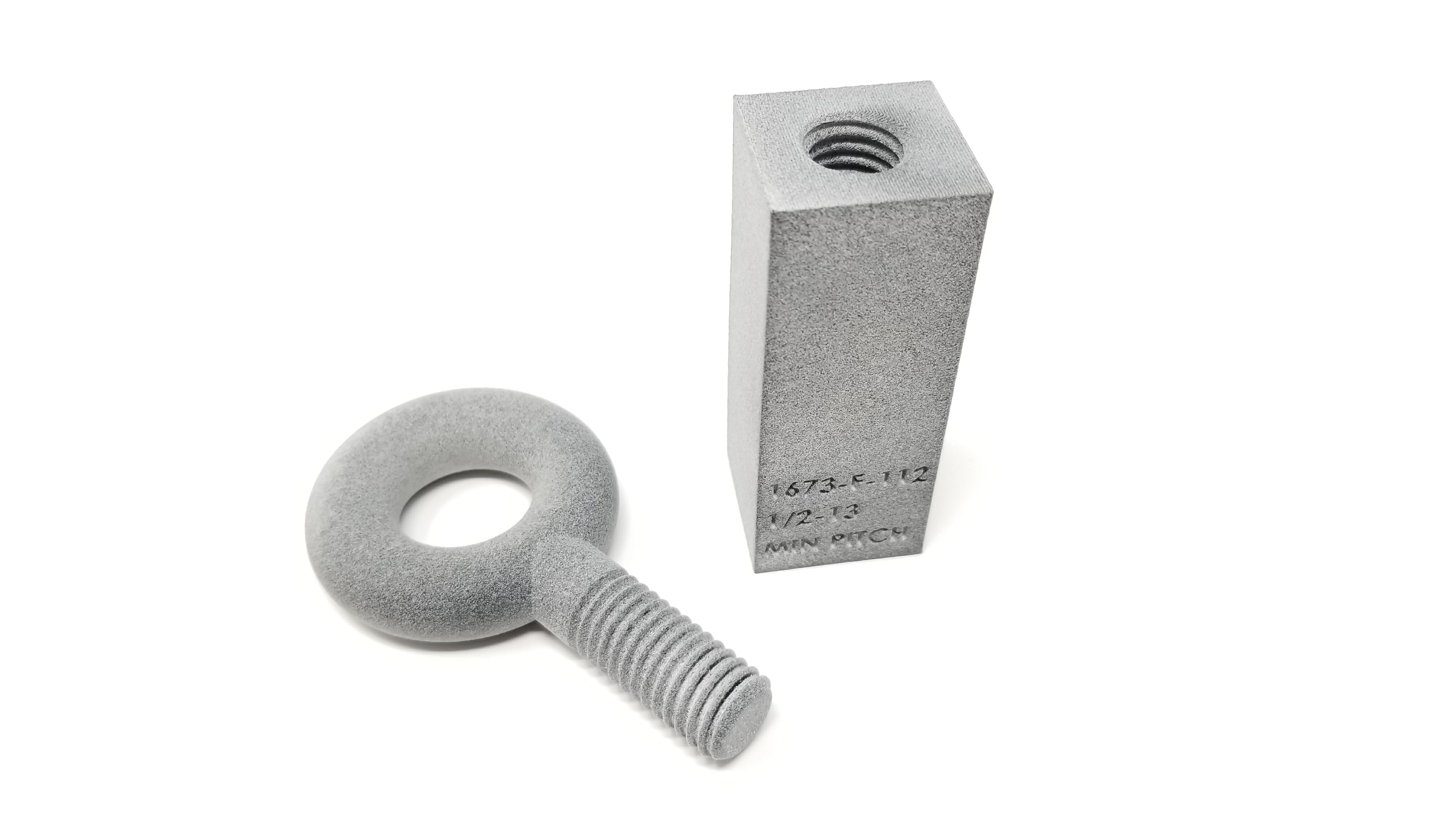
Printing the threads in 3D printed parts is possible, and as you can see from the testing video below it works quite well even in high load end use applications. Through testing we have done here at F3DP we have found its possible to print threads as small as 6-32 or M3 into 3D printed parts. This page will teach you how to go about designing in these threads for 3D printed parts.
Thread Strength Testing: Nylon 12 Material
Tensile strength test of MJF parts with larger printed in threads
Tensile strength test of MJF parts with smaller printed in threads
Thread Strength Testing: TPU Rubber Material
Tensile strength test of TPU Rubber MJF parts, helicoil thread insert vs. printed in thread
What machines is it possible to print threads into 3D printed parts with?
| 3DP Technology | Minimum Printable Thread Size (INCH) | Minimum Printable Thread Size (METRIC) | Notes |
| HP Multi Jet Fusion (Nylon 12) | 6-32 | M3 | Best 3DP machine for printed threads. |
| HP Multi Jet Fusion (TPU Rubber) | 1/4-20 | M6 | |
| SLS | 1/4-20 | M6 | |
| PolyJet | 6-32 | M3 | |
| SLA | 8-32 | M4 | Holes must be printed vertical on machine or they will have support in them. |
| CLIP | 8-32 | M4 | |
| FDM | 1/2-13 | M12 | Not recommended, holes must be in the vertical orientation on the print bed of the machine. |
This guide will be specifically talking about threads for 3D printed parts coming off of the HP MJF technology. The MJF machine is unique in that it allows for very fine features to be printed in any orientation without the need for support while still being able to use high strength materials like Nylon. The next closest technology that would be able to produce threads would be SLS, but these machines can’t capture the same level of detail as the MJF so they are limited to 1/4-20 or M6 threads or bigger. Then there are the liquid polymer machines like Polyjet, SLA, CLIP, DLP, ect. These machines can absolutely print threads down to 8-32 or M4, but the hole must be oriented in the vertical direction from the print bed. If the hole is horizontal it will end up with support in it and the 3D printed thread will not turn out. Lastly, FDM technology is not suited to print in any threads under 1/2-13 or M12, and they have to be oriented vertically from the machines print bead.
What software is used to design threads?
Our in-house engineering group works with all the major CAD software’s, but the one that is the easiest to use for adding threads into a 3D printed part is Solidworks. The reason for this is that it has a built in tool that will automatically add in the correct thread profile for you. For this reason this guide is built around this software, and the following video is a tutorial that will walk you through how to add threads in 3D printed parts:
How To Design 3D Printable Threads – NUT
How To Design 3D Printable Threads – BOLT
Here is a really good tap / drill chart for reference.
For those not using Solidworks for their CAD design software we have also collected thread design how to video’s for a lot of the other major CAD design software’s on the market:
Designing 3D printable threads with Autodesk Fusion 360 Designing 3D printable threads with Autodesk Inventor Designing 3D printable threads with CATIA V5 Designing 3D printable threads with PTC Creo Designing 3D printable threads with Google SketchUp Designing 3D printable threads with OnShape Designing 3D printable threads with TinkerCAD Want a second set of eyes to check over your design or have a question? We offer free Design for Additive Manufacturing (DFAM) consulting for our customers:
Have questions?
Contact us:
Sales@Forerunner3d.com – 231.722.1144
Click here to go to the 3D Printing Machines & Materials page