The following HP Multi-Jet Part Design Guide has been assembled to help users of the MJF process for the manufacturing of their parts better understand how to go about designing parts to harness all the advantages while minimizing the limitations of the MJF process. For more information on the Hewlett-Packard (HP) MJF 3D Printing process check out our process page or our how it works page for this technology.
Saving out high quality part files:
Before sending a job to a 3D printer, the model to be printed needs to be tessellated. That means that its geometry needs to be converted into triangles, which are used by the printer to create layers. It is very important to pay attention to this step: if not done correctly, it can cause problems such as inaccuracy or slow processing. Standard formats in the additive manufacturing industry include 3MF (with more information about the model) and STL. A normal file size for a model is about 1–30 MB, but the size depends on the type of software that created it, the number of triangles, the number and level of details, and so on. When exporting to STL in a CAD package, you are often required to introduce some parameters such as angle tolerance and deviation chord height. These parameters define the resolution and file size of the part. The following tips will help you to export with the best surface to file size ratio.
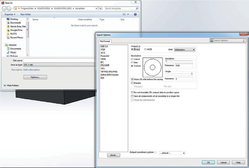
Example: SolidWorks settings
- Click File > Save As.
- Select STL (*.stl) as the file type.
- Click Options.
- Choose the Binary option. Binary files are smaller than ASCII files for the same tessellation.
- Choose Custom resolution.
- Set the deviation tolerance to 0.005″ (0.127mm).
- Set the angle tolerance to 10°.
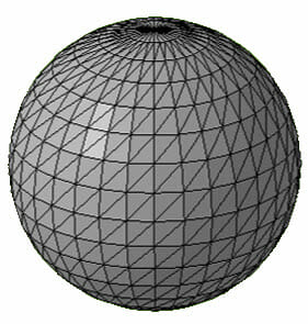
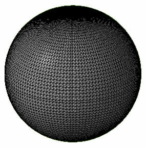
Common STL File Problem: Too many or too few triangles
Too many triangles are difficult to process and, when a certain size is reached, the extra triangles do not provide any further accuracy. For this reason, an excess of triangles could increase processing time for no benefit. Triangulation of a surface causes faceting of the 3D model. When the parameters described in the last section are used to output an STL model these issues are eliminated. Also, specialized 3D printing software like Magics can be used to eliminate unneeded triangles from an STL file without effecting its accuracy or quality.
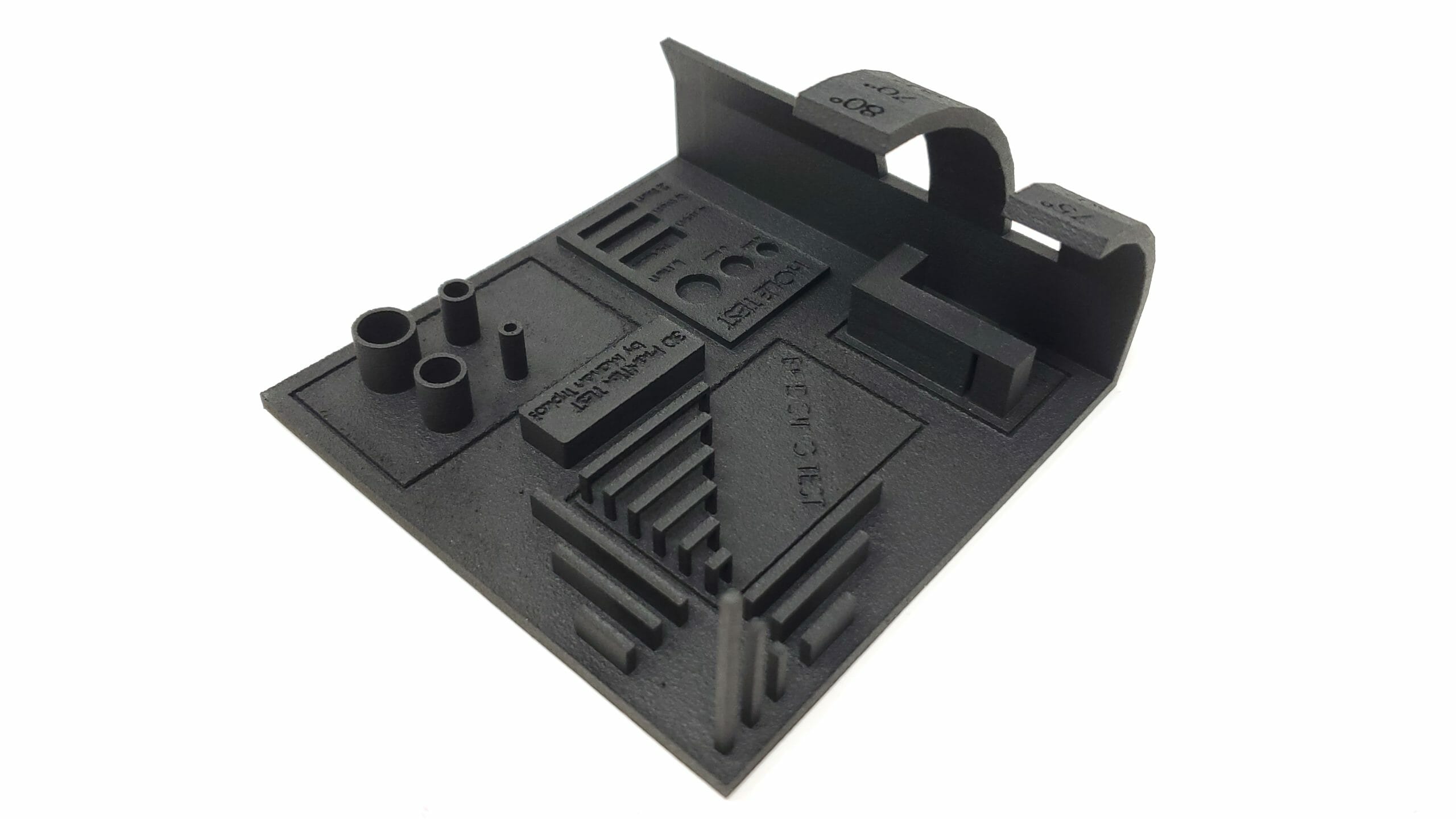
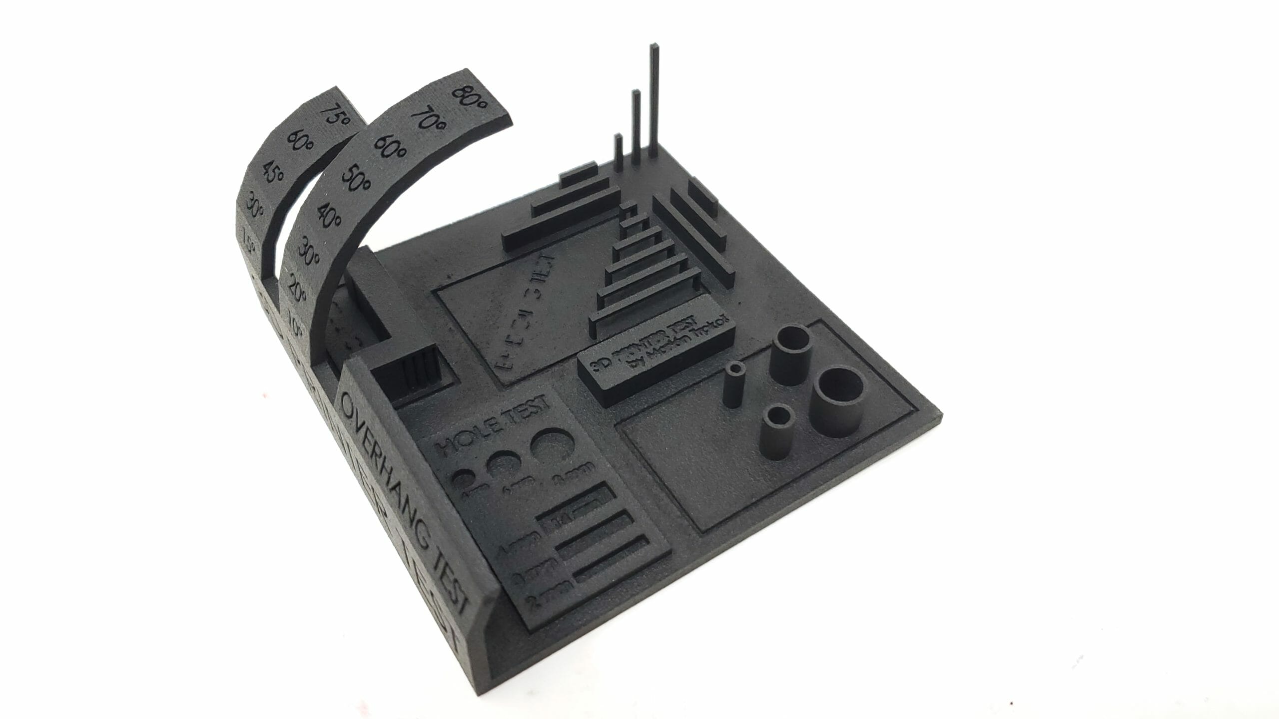
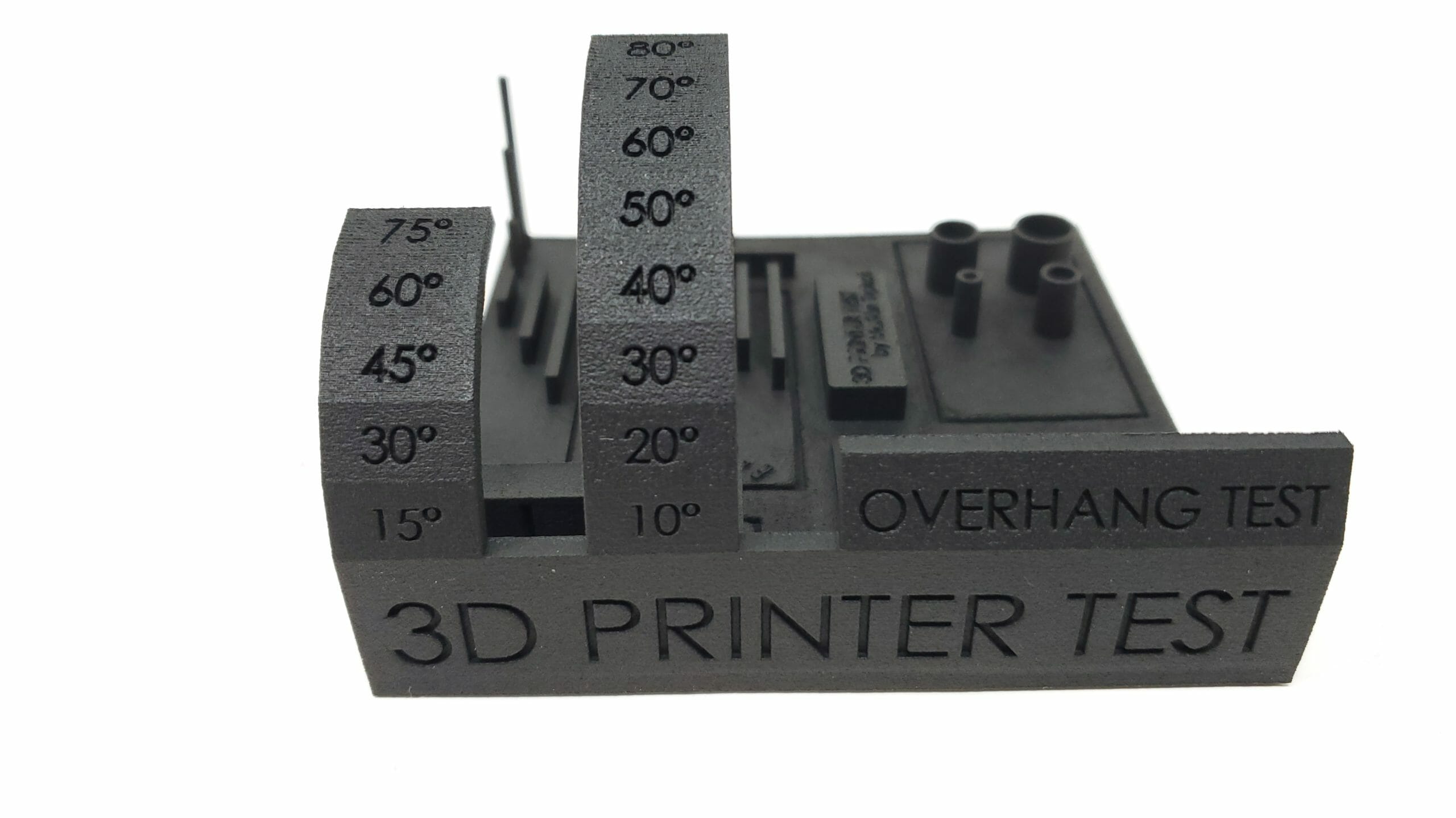
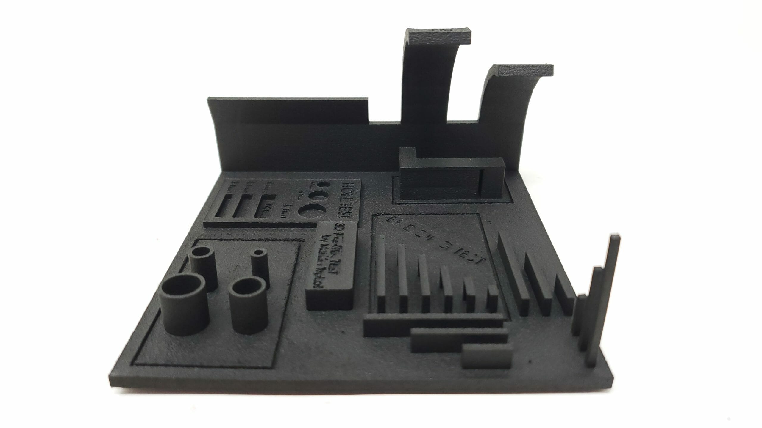
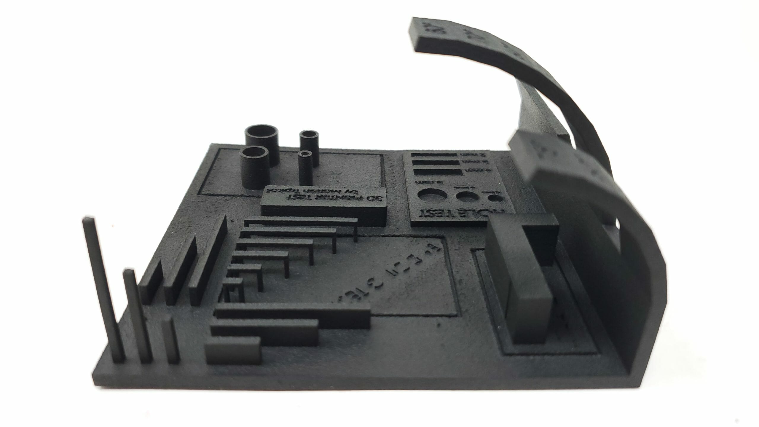
Minimum Feature Sizes for Parts:
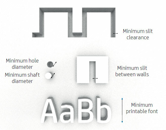
There are some specifications to bear in mind in order to avoid issues in parts, and to achieve the best quality. The minimum printable features in planes X, Y, and Z are as follows:
| Inches | Millimeters | |
| Minimum hole diamiter in a .039" (1mm) thick wall | .02" | .5mm |
| Minimum shaft diameter of a .39" (10mm) tall shaft | .02" | .5mm |
| Minimum printable font size (both standing out and cut in) | .1875" | 4.75mm |
| Minimum clearance at 1mm thickness | .05" | 1.27mm |
| Minimum slit between walls | .025" | .635mm |

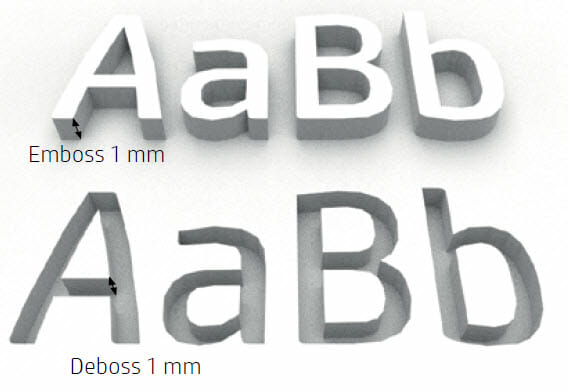
Text / Logo Design:
Multi Jet Fusion technology allows you to print text and logos with a very high resolution and definition. For the best possible output of any text included on the part we recommended it having a height of at least .2″ and to be cut into the part at least .05″ deep (or high if embossed).

Dimensional Accuracy of Parts:
The general rule of thumb for the MJF process is +/- .010″ for the first 1 inch, +/- .005″ per inch thereafter. For a much more detailed breakdown of 3D printed part accuracy beyond what is detailed in this HP Multi-Jet Part Design Guide please see our page dedicated to this topic.
Part Structure Options:
We have included 3 of the most popular examples / options of the internal structures that can be used with MJF parts in this HP Multi-Jet Part Design Guide:
Lattice:
Multi Jet Fusion allows you to print topology-optimized, generative designs or even small lattice structures. This kind of design helps to reduce the weight of the part and the quantity of material used, which not only reduces the cost of the part but also helps to reduce the operating cost in applications that are very weight-sensitive.
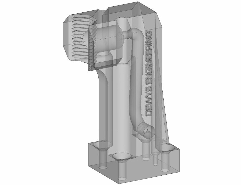
Hollow:
Parts can be printed hollow, this greatly recuses the amount of heat that builds up in the part during the printing process allowing for more accurate parts and also allows them to be lower cost (less raw material and fusing agent are used). One down side to consider is that due to the parts being hollow they can be a bit weaker. If the parts printed are hollow, drain holes can to be added to the design to remove the unsintered material. The minimum recommended diameter of these drain holes is .25″ [6.35mm] and a minimum of 2 of them is recommended to allow for compressed air depowdering. We can also leave powder trapped in the parts, this helps save cost on complicated depowdering / plugging of parts but if the part needs to be dyed black this is not recommended as it causes the parts to float. At F3DP we utilize a specialized software called Magics that allows us to very easily and quickly hollow and add drain holes to parts as needed. We offer this for free to our customers and can work with you to make sure you original design intent is maintained.
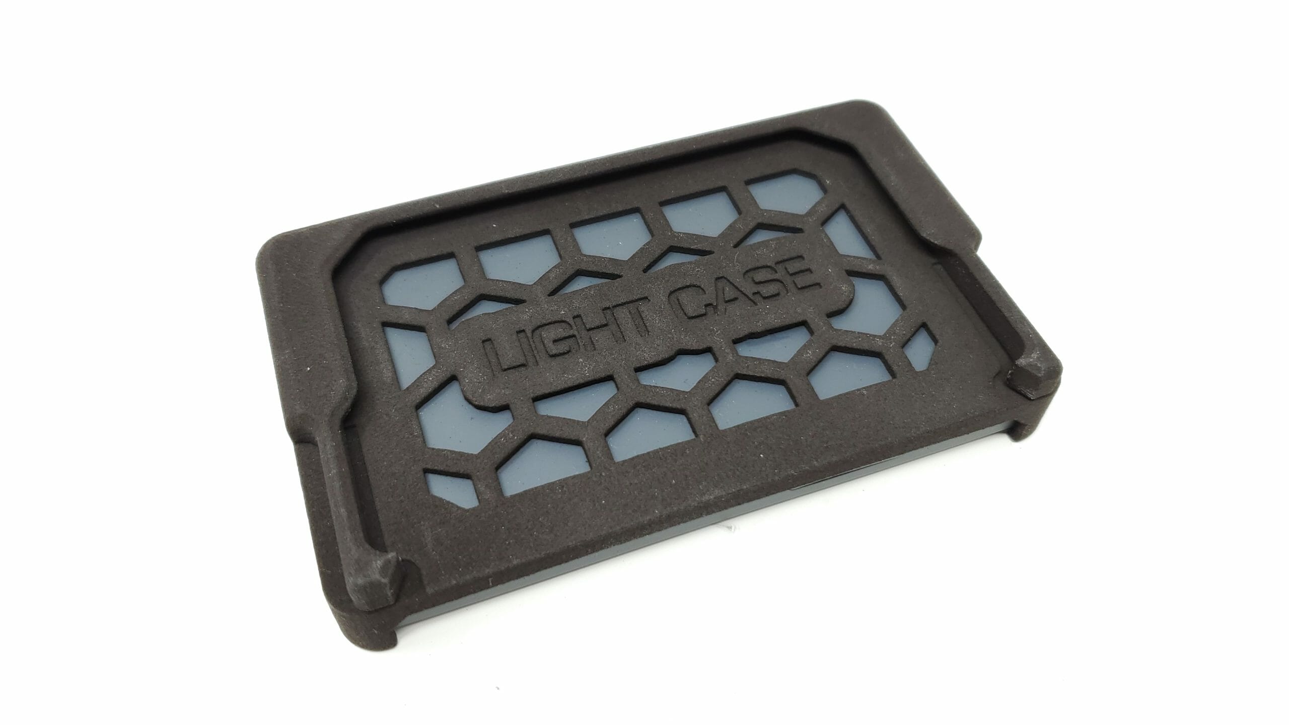
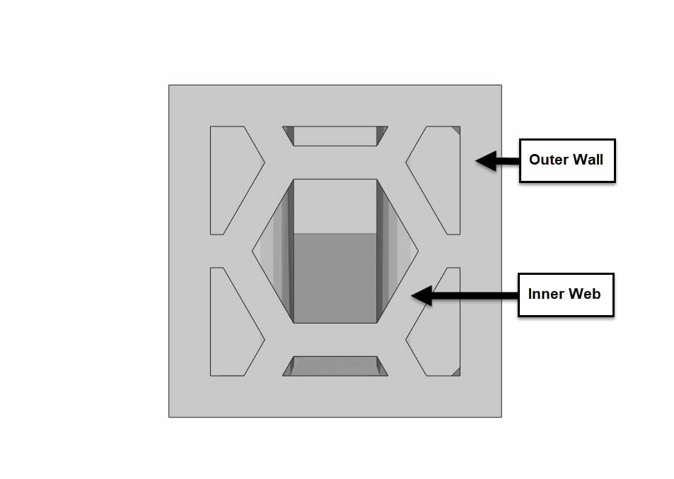
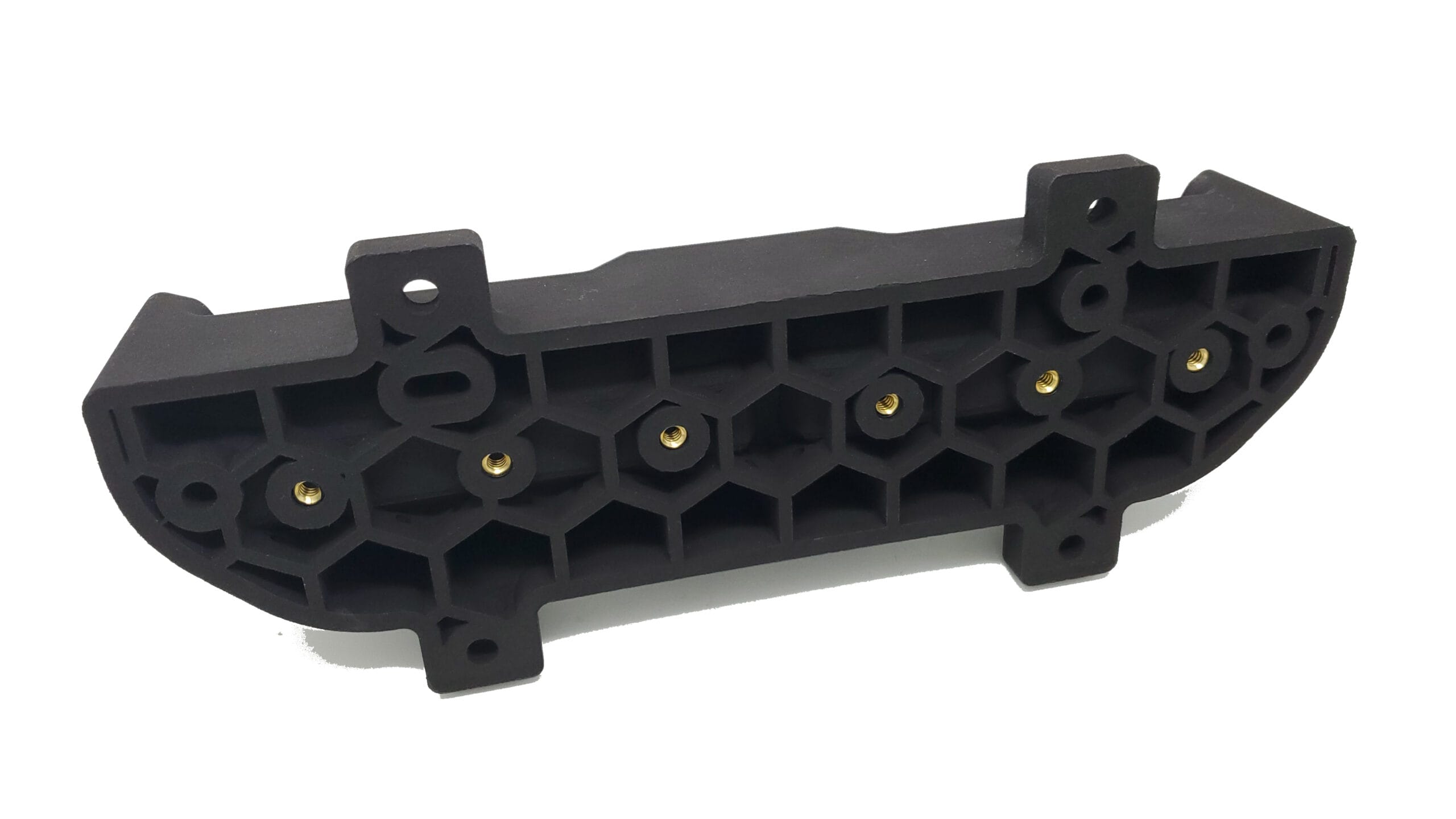
Honeycomb:
This option is a combination of the benefits found in hollowing a part combined with the benefits of a latus structure. It keeps the part very strong but cuts out a large volume of material saving on both cost and loss of accuracy due to high heat during the build. The only concession that needs to be made to a parts design is that one end of the honeycombed region needs to be left open so the cells can be depowdered. If this is not a option please consult with F3DP directly on your part as there may be other alternative designs we can propose to you. At F3DP we utilize a specialized software called Magics that allows us to very easily and quickly honeycomb parts as needed. We offer this for free to our customers and can work with you to make sure you original design intent is maintained. The following table will give you basic dimensions that should be used for designing honeycomb features should you choose to design them yourself:
| Outer Wall Thickness | Inner Web Thickness | |
| Light Duty Application | .125" | .100" |
| Medium Duty Applications | .1875" | .125" |
| Heavy Duty Applications | .25" | .1875 |
Design of Part Assembly Features:
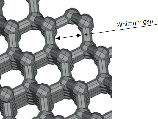
Minimum gap between parts to be assembled after printing
Sometimes a pair of printed parts need to fit together for the final application. In these cases, you are recommended to have gaps of at least .015″ [0.4mm] (±.008″ [0.2 mm] of tolerance of each part) between the interface areas that should fit together, in order to ensure correct assembly.
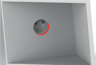
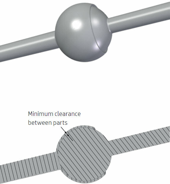
Minimum spacing and clearance between parts printed as assemblies
Assembly parts that are printed together should have a minimum clearance of 0.027″ (0.7 mm). Parts with very thick walls above 2″ (50 mm) should have a higher gap in order to ensure proper performance.
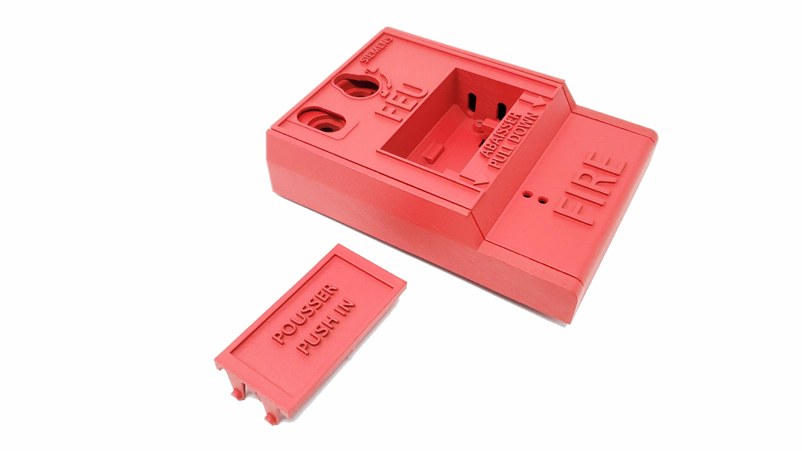
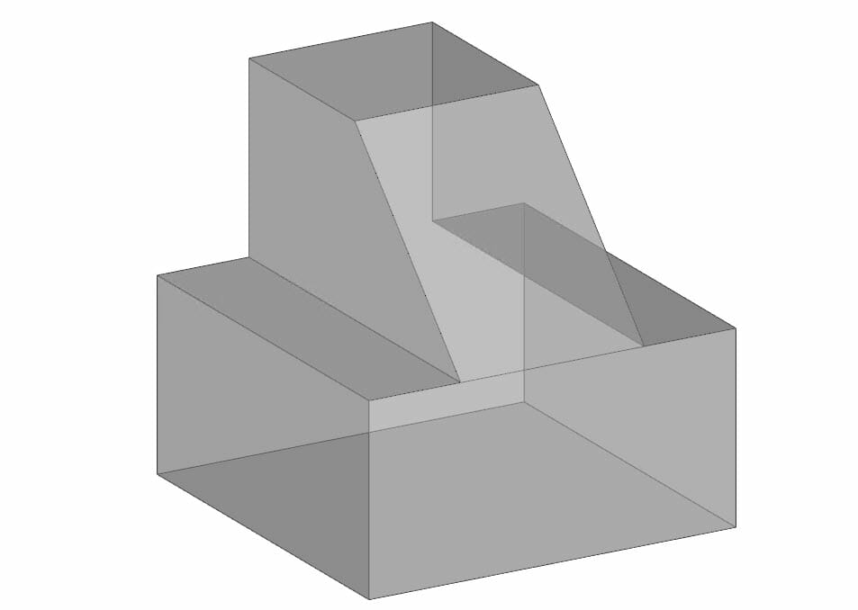
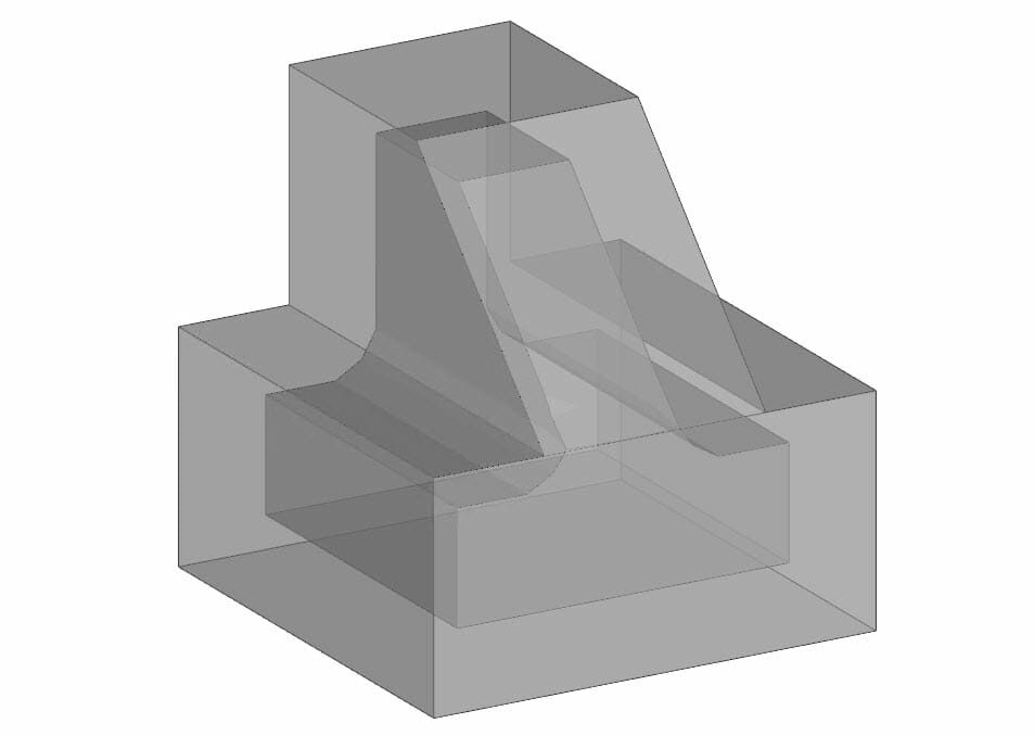
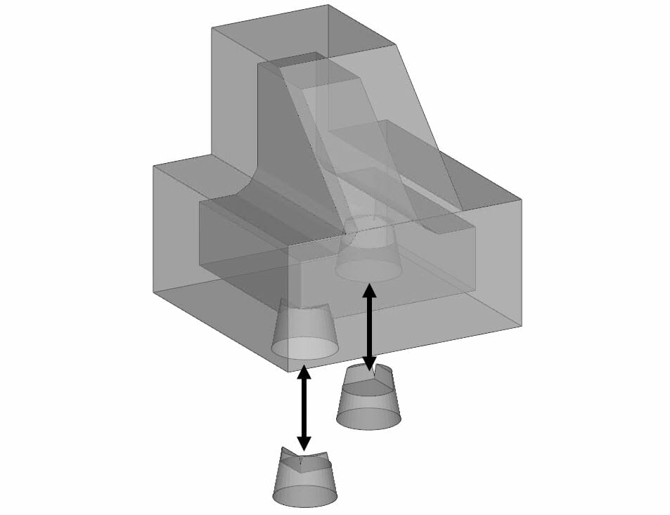
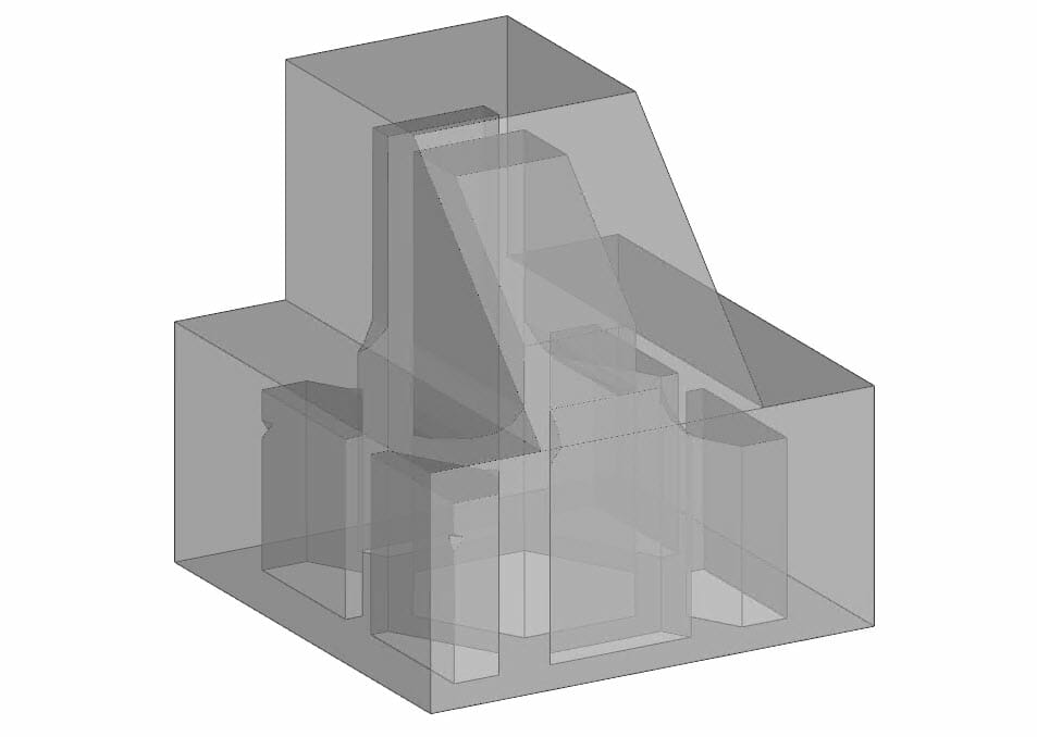
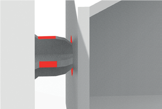
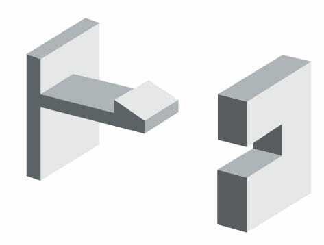
Glue Joints
Parts larger than the maximum build size can be printed with Multi Jet Fusion by splitting them into different parts. They can then be joined together by gluing, welding, or by pin inserts. If you plan to glue parts together, you are recommended to include interlocking features such as those shown in the pictures below: as a guide to position the parts, to help them to bond together, and to facilitate the gluing process. Remember to leave an additional space of .004″ [0.1mm] – .008″ [0.2mm] between parts for the glue, in addition to the minimum spacing between parts printed as assemblies (see above). At F3DP we utilize a specialized software called Magics that allows us to very easily and quickly split parts to make glue joints as needed. We offer this for free to our customers and can work with you to make sure you original design intent is maintained.
We recommend using Loctite HY4070 glue for assembling HP MJF parts. Here is a 3D Printing Glue Strength Guide.
A customer requested to know how well our standard glue joint would hold up to repeated shock loads. We devised this simple test to prove out the strength of a HP MJF glue joint as well as do a metal vs Nylon wear test at the same time. Here are the results of that testing we are including in this HP Multi-Jet Part Design Guide:
Dowel holes and Dowel Slots For Assembly
There are some general rules of thumb to keep in mind when you are adding in dowel features for printed parts. Unlike with traditionally machined components you need to account for the inherent inaccuracy of 3D printed parts. Please see our dedicated page on this topic for more information.
Double Sided Sticky Tape For Assembling Parts After Printing
Another option for attaching MJF parts to each other is to use double sided tape. Here is a page with all the strength testing data we have collected for a few different options of tape available from tesa.
Design for Depowdering Ducts / Internal Passageway’s
When designing long (over 6″ [152mm]) and twisting (more than one 90 deg turn) passages for things like compressed air or vacuum it is recommended to keep the minimum diameter of the passage to .1875″ if at all possible (the bigger the better). To remove material from narrow ducts, consider designing and printing a strip or a chain through the duct. When the parts have been printed, you can pull out the chain to dislodge most of the material. Any remaining material can be removed by the normal cleaning process. If duct work is small in diameter or complex in routing its recommended to consult with F3DP on its design to incorporate more advanced best practices (clean out ports) into the design.

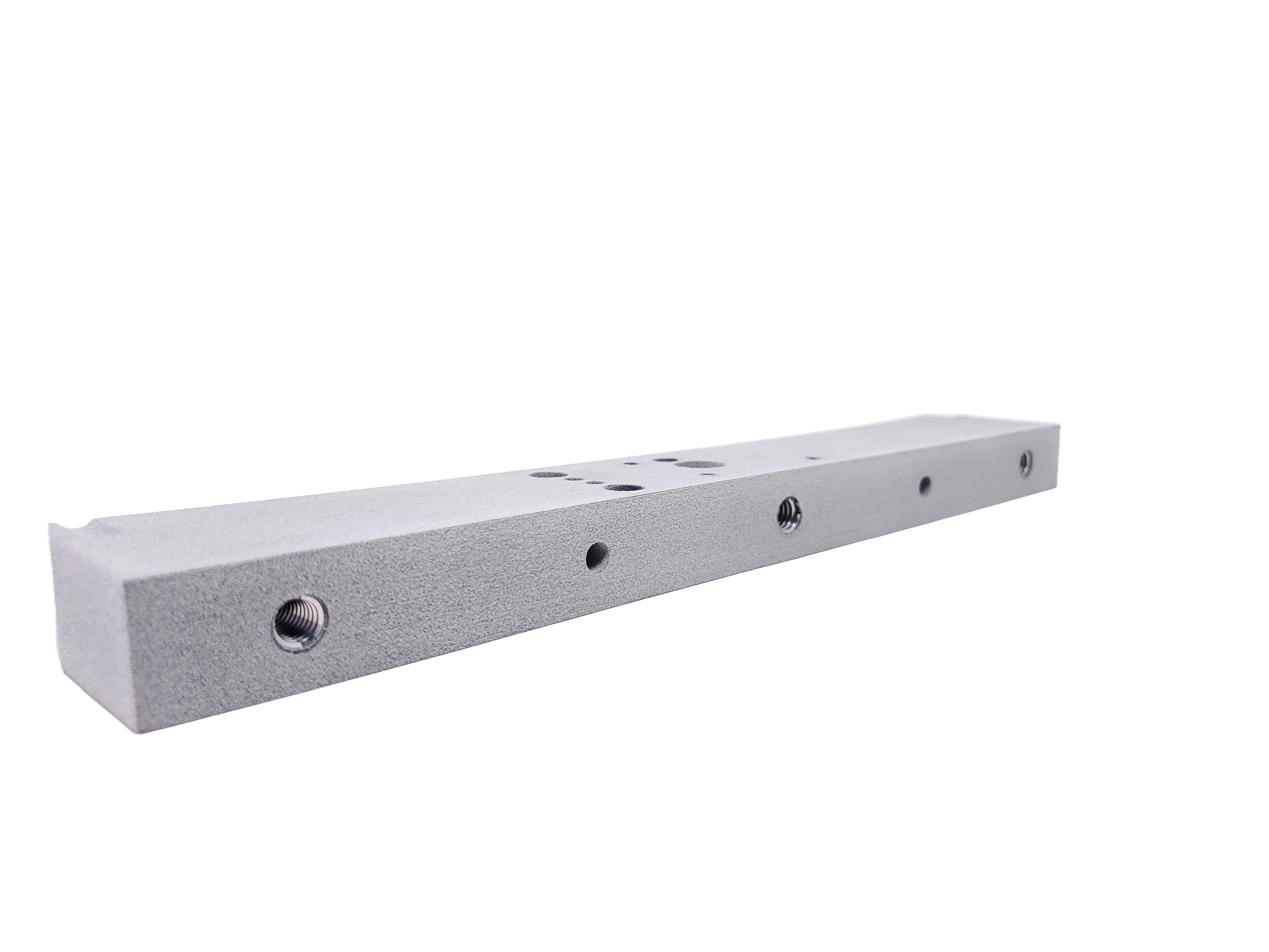
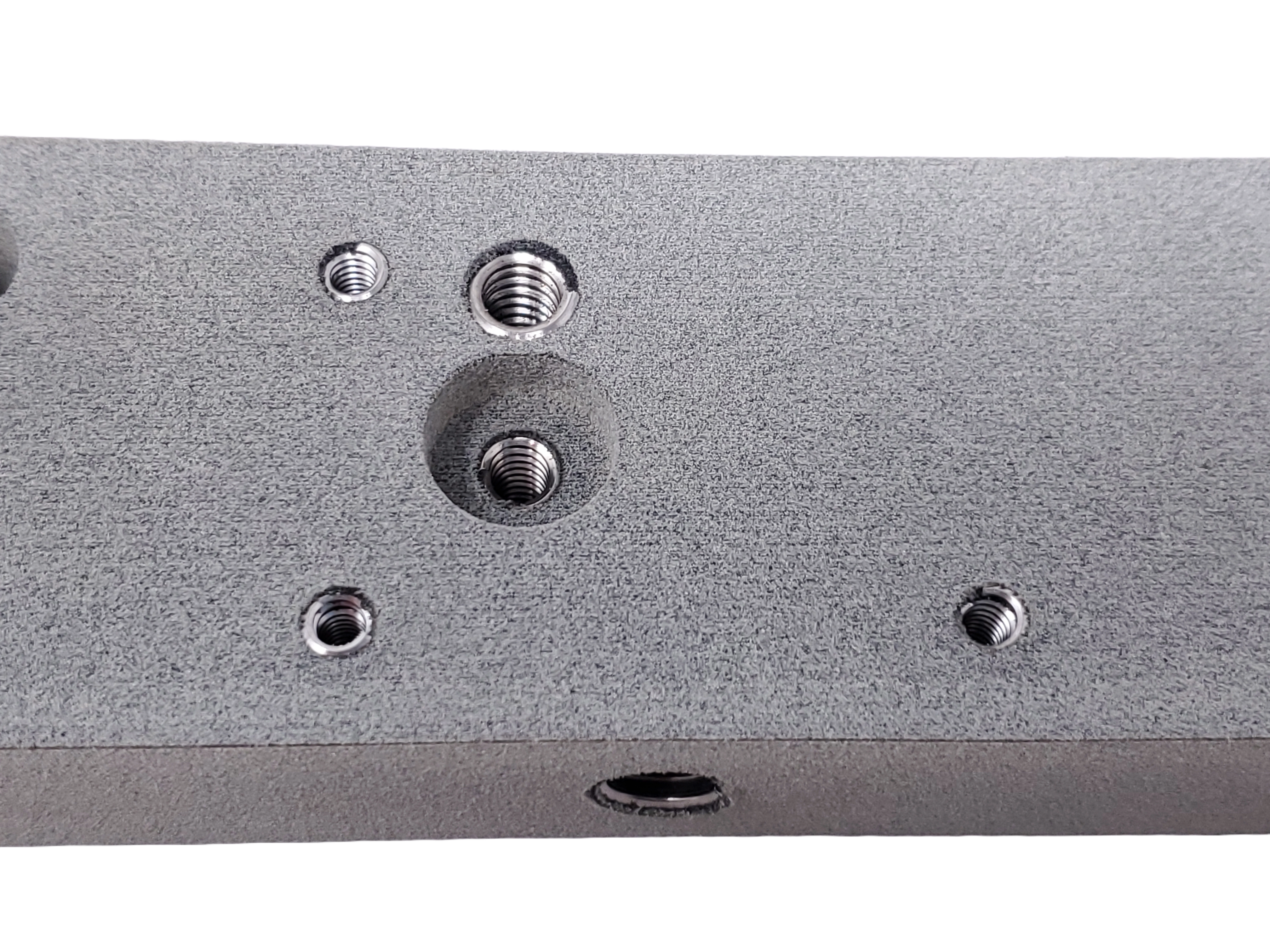
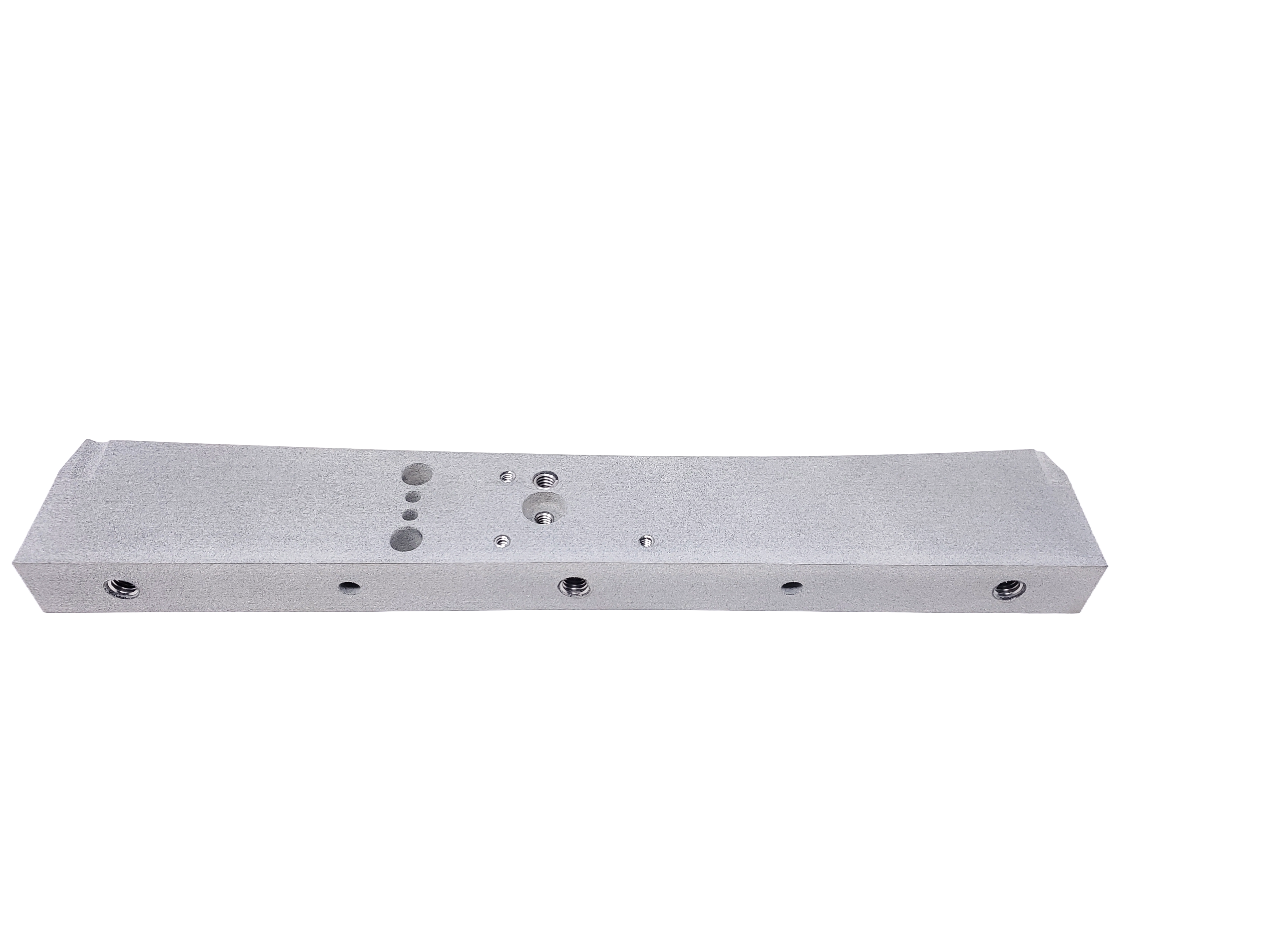
Thread Design Options:
Printing Threads Into The Part
One of the most useful abilities of the HP MJF technology is its ability to print threads directly into a part. This saves the need to use a insert like a Helicoil or heat set insert. It also eliminates the need for doing secondary tapping operations after the part is printed. In our experience with production parts the use of a printed in thread can save days worth of extra shop time spent tapping holes.
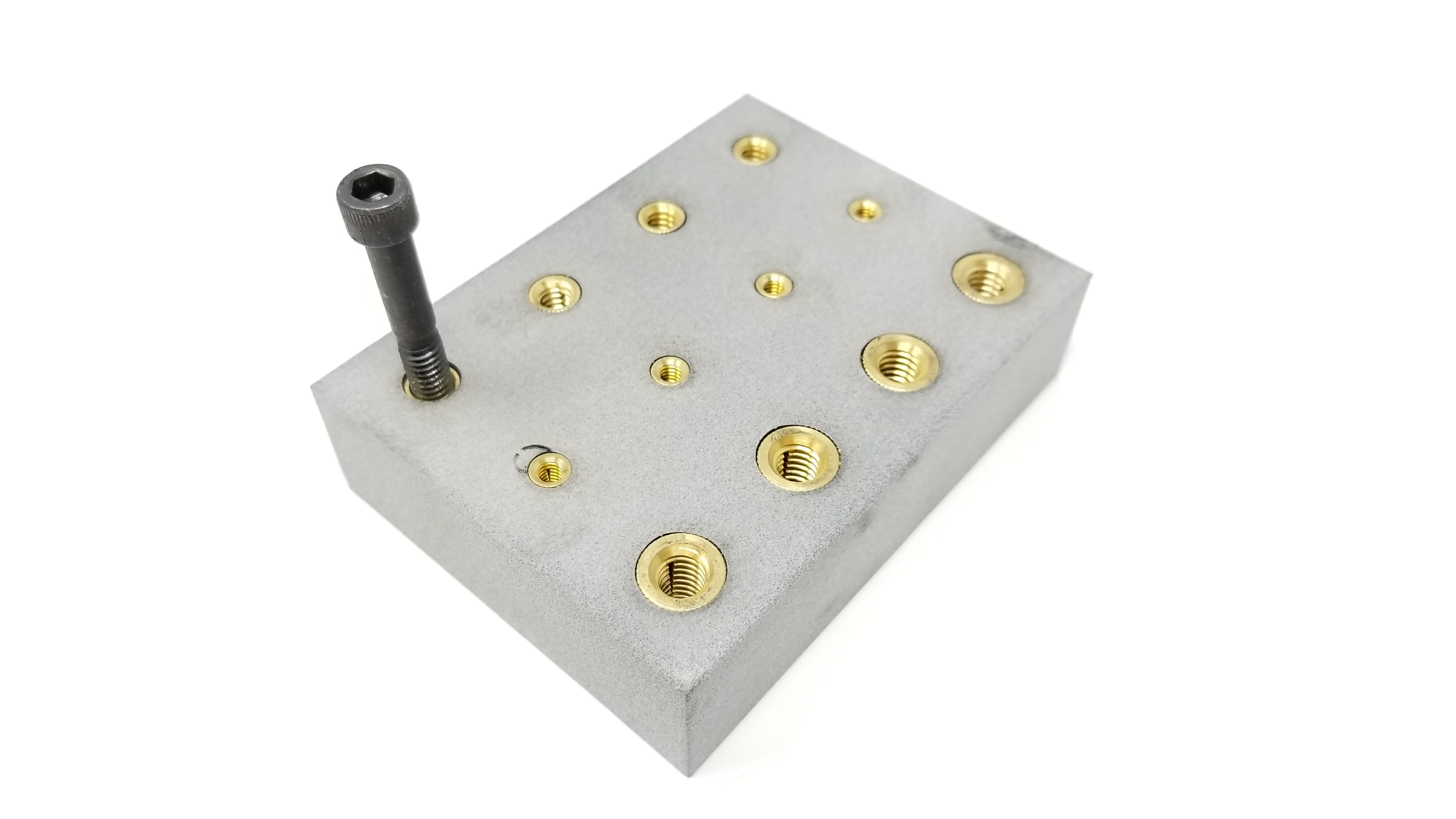
Using Threaded Inserts In Parts
Multi Jet Fusion parts are made of thermoplastic materials and can be re-melted and re-formed once printed. Heat-staking and ultrasonic installed inserts are recommended for thermoplastic materials; however, pressin, self-threading and expansion inserts may also be used in some applications. The following information is being provided in this HP Multi-Jet Part Design Guide to help you with selecting the proper insert for your application:
Compatible Materials
These are HP MJF materials that have been tested with inserts and confirmed to work and hold up:
Heatset Inserts DO NOT work with M95A TPU Rubber, Helicoils do work but not well, printed threads work extremely well in TPU parts.
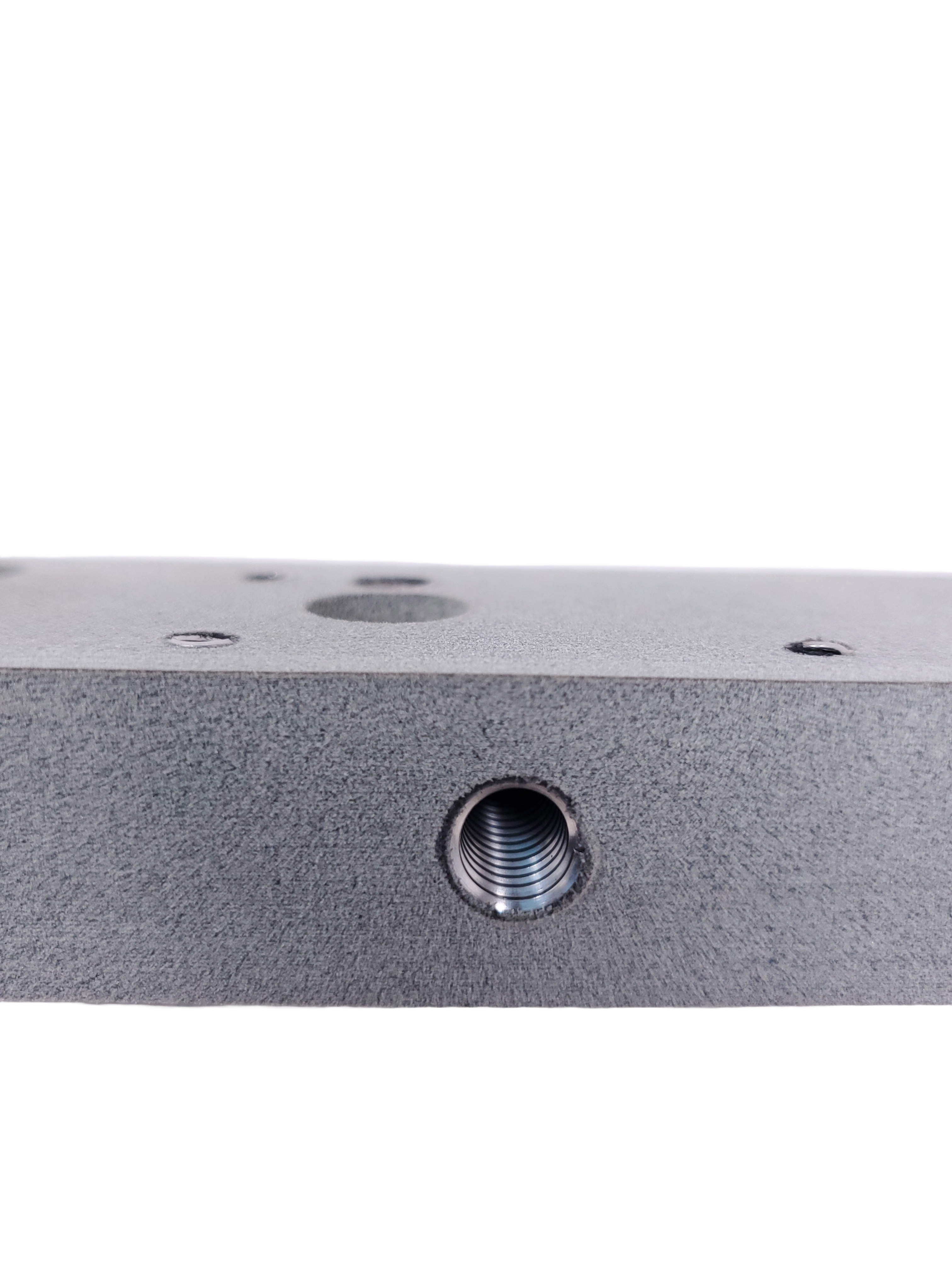
Hole diameter
The hole diameter is very important to achieve the desired strength, oversized holes will result in a reduction of the joint strength and undersized holes can potentially crack the part. Multi Jet Fusion parts have a tolerance of +/- .005″ in small features and this is usually above the supplier specifications. For this reason, it is important to select a type of insert that is compliant with hole deviations and a lower performance should also be expected.
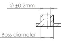
Wall thickness
Traditionally a boss diameter is two times the external diameter of the insert for inserts under .23″ [6 mm], a .11″ [3 mm] wall thickness applies for all larger inserts. Exceptions include applications incorporating supported bosses, reinforced materials, and heat installation. Special consideration should be given to cold press installations where stress will be increased and may require larger boss diameters.
Mating hole
It is important that the insert bears the load, and not the plastic, to avoid jacking the insert out. The mating component hole should be smaller than the face of the insert but still allow the connecting threaded fastener sufficient space to function normally. The mating component must also withstand the stress generated by the clamping force. In instances where the mating component will also be plastic, the use of a secondary insert or collar should be considered to avoid creep.

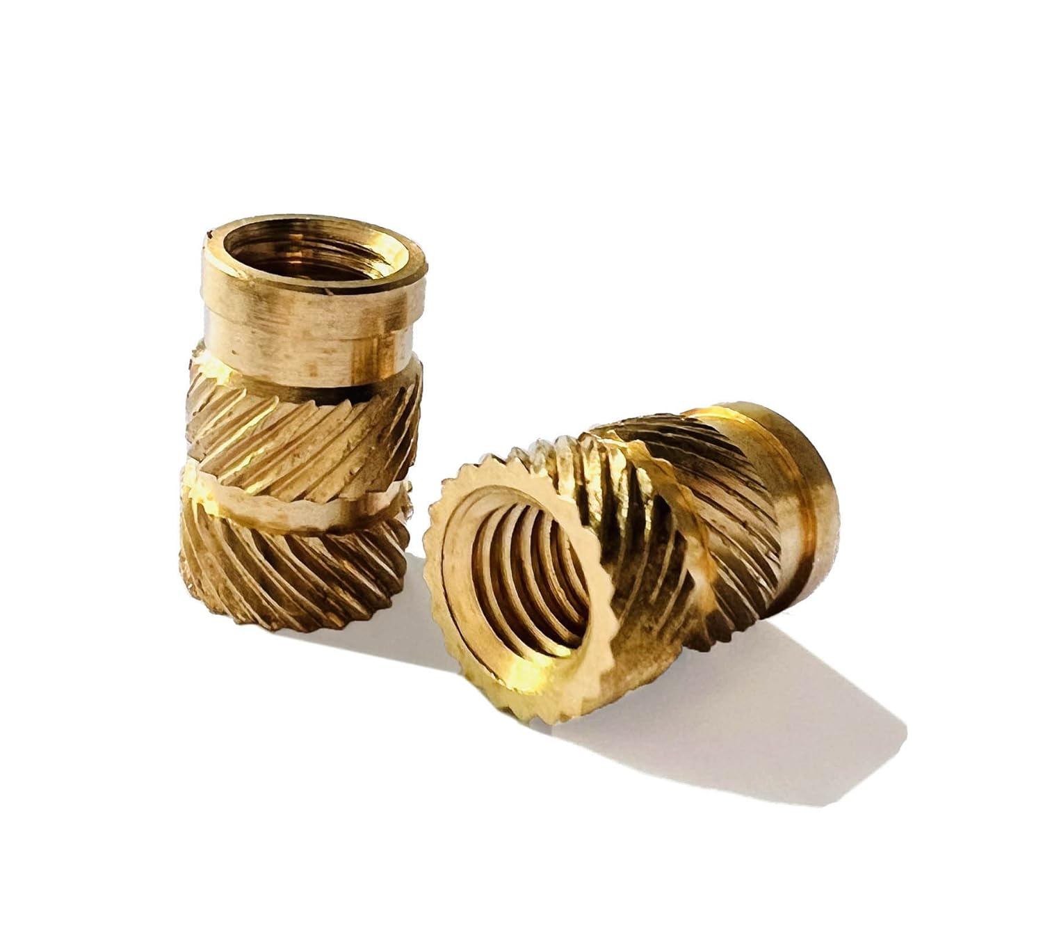
Types of insert
The recommended insert for Multi Jet Fusion parts depends on the type of installation and the geometry of the insert. This is a summary of the main types of insert available for plastic parts:
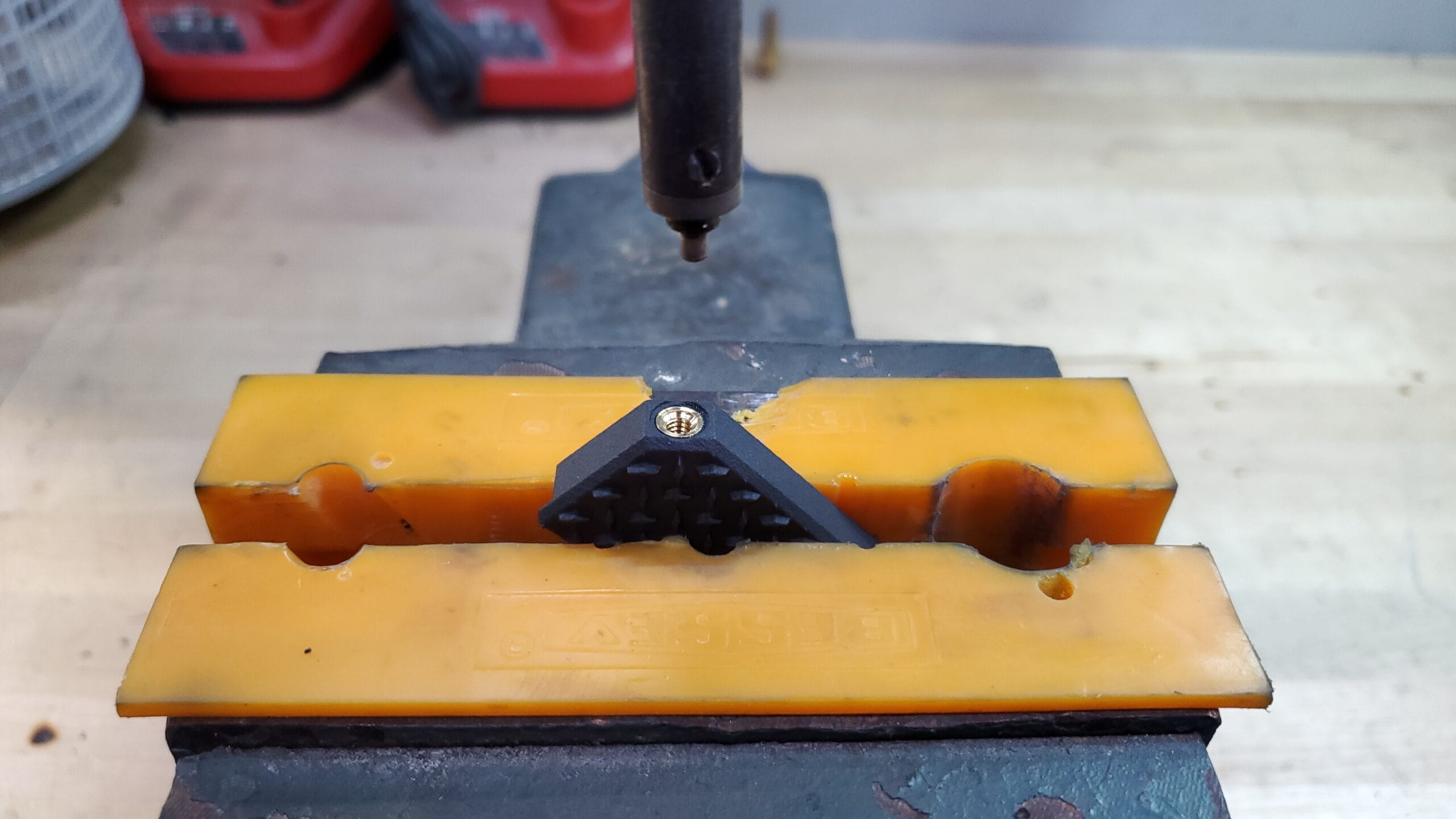
- Heatset inserts
- The insert is positioned into the printed or drilled hole and a heated tip is then inserted into the inside diameter of the threaded insert. Localized melting begins to take place and with the downward pressure, the insert is installed. Plastic flows into the varying undercuts and knurls. The main benefit of thermal installation inserts is the superior strength. For detailed instructions on how to design holes for heat set inserts and pullout strength testing please check out our detailed guide on the topic.
- Cost to install: $$
- Ultrasonic insert
- The insert is positioned into a printed or drilled hole and an ultrasonic horn then contacts the insert and begins to vibrate the insert. This vibration creates frictional heat which melts the plastic allowing the horn to lower the insert into position. These inserts use the same principle as heat installation but there is less risk of over melting the allocating holes providing better installation accuracy.
- Cost to install: $$
- Press-in inserts
- This type of insert is economical (no specific tooling, heat, or ultrasonic is required) and easy to install, but is recommended for non-critical applications as these inserts have a habit of falling out or working loose.
- Cost to install: $$
- Helicoil inserts
- Helicoil are a great way to install a metal thread into a plastic part. While they have a lower pullout strength then heat set or ultrasonic inserts they do offer a metal thread that will hold up to repeated assembles and disassembly’s better then a plastic thread would.
- Cost to install: $$$$ – These inserts have the most steps involved to install them, this drives up labor costs for them.
- Helicoil can be used with M95A TPU Rubber in order to put a metal thread into parts made from this material
- E-Z Hex inserts
- E-Z Lok Hex insets are a great way to install a metal thread into a M95A TPU Rubber. Once installed they are very strong and resistant to high pull out forces.
- See our full design guide on how to use these inserts and what kind of pull out forces you can expect on our dedicated topic page.
- Cost to install: $$ – These inserts are very quick and easy to install.
- E-Z Lok Hex inserts are only recommend for use with M95A TPU Rubber as its aggressive self tapping threads can cause cracks with hard plastics like Nylon 12.
Snap-Fit Design Options:
Snap fits provide simple and economical way to assemble parts, often saving time in assembly. This is possible with a protruding feature on one part, which flexes during assembly into a groove or slot in the mating part. When fully seated the protruding feature returns to its initial position.
Types of Snap-Fits
Cantilever Snap-Fit
The cantilever snap-fit is the most commonly used type of snap-fit. It consists of a cantilever beam with an overhang at the end. In this type of snap-fit there is a direct relationship between the robustness of the assembly and the strength of the snap-fit.
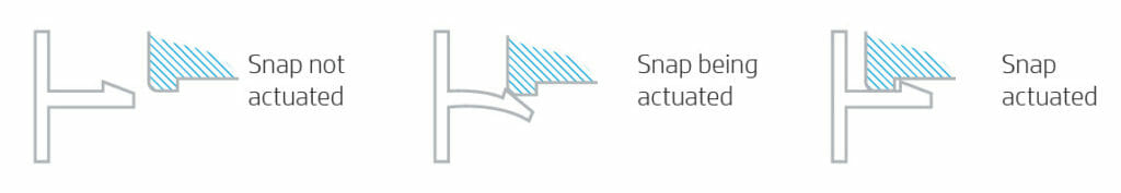
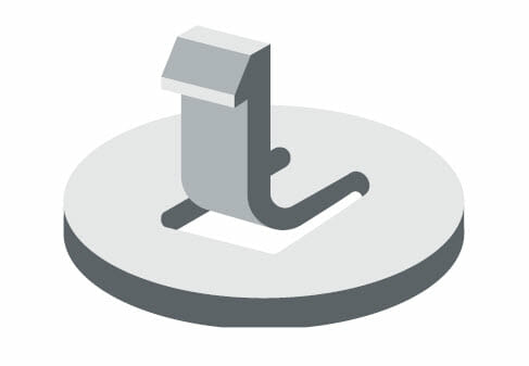
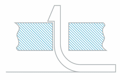
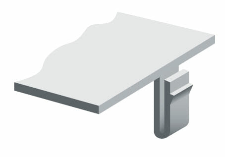
L-Shaped Snap-Fit
When it is not possible to design a cantilever snap-fit without compromising the robustness of the assembly and the strength of the snap-fit due to material or geometrical constraints, an L-shaped snap-fit can be an alternative. Adding a groove to the base
of the snap-fit increases its flexibility while reducing the strain on the beam, compared with a cantilever snap-fit.
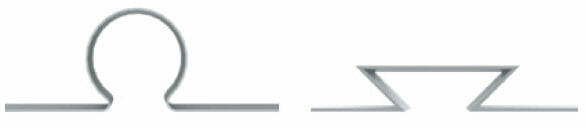
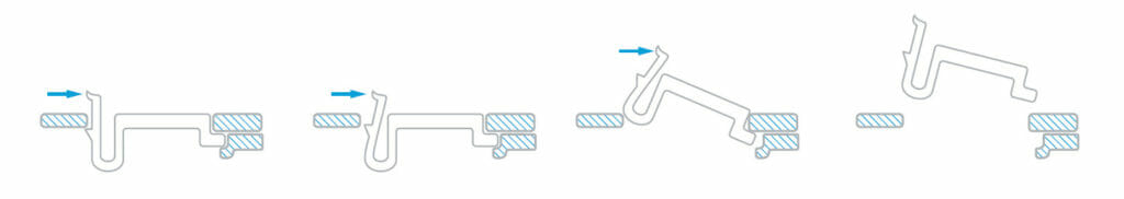
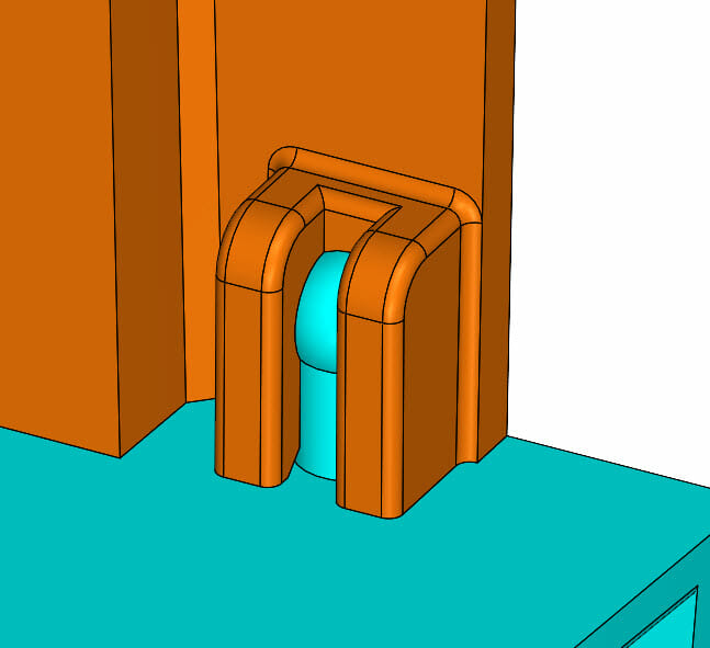
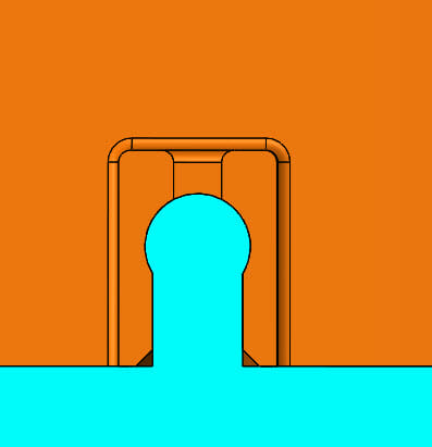
U-Shaped Snap-Fit
The U-shaped snap-fit is another alternative to the cantilever snap-fit when it is necessary to increase the snap-fit flexibility within a reduced space. This U-shaped alternative is extremely flexible, and thus easier to remove. This type of snap-fit is usually used in cases where the parts need to be pulled apart repeatedly or when two parts don’t require a lot of force to stay in position (e.g., in a battery compartment lid).
Annular Snap-Fit
The annular snap-fit is an assembly method usually used between two cylindrical or ring-shaped parts or between two rotationally symmetric parts, where the deformation required to assemble or disassemble the snap-fit is made in a 360º direction at the same time.
With this assembly method, one part is designed with an undercut and the other is designed with a mating lip. The joint occurs through the interference between both parts during the assembly operation.
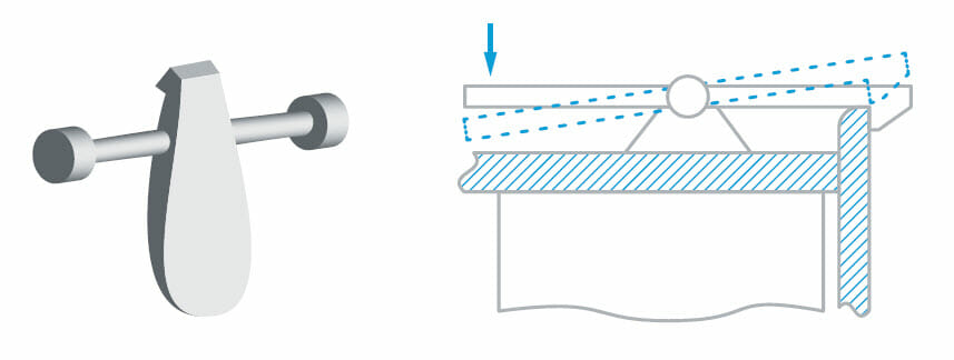
Torsional Snap-Fit
The torsional snap-fit is an assembly method where the flexible point is in a torsional bar instead of the self–snap-fit body. When the torsional bar is pushed down, it turns slightly and opens the joint.
Basic Snap Design Guidelines
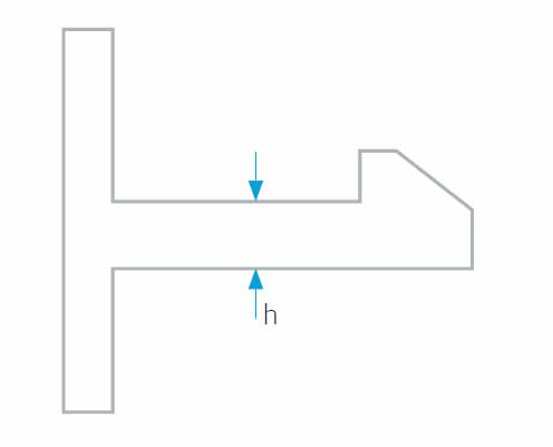
Minimum Thickness (h)
The minimum recommended thickness at the base of the cantilever is 1mm (0.04in).
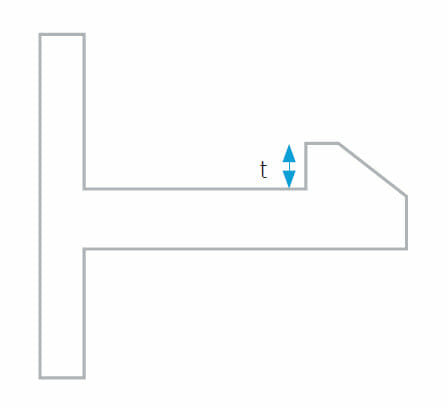
Minimum Overhang (t)
The minimum overhang depth (t) should be at least 1mm (0.04in)
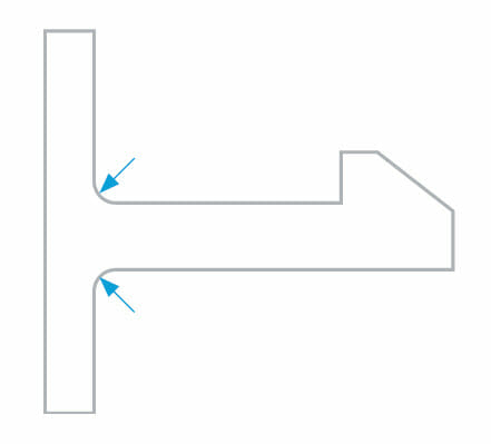
Corner Treatment
It is recommended to add a radius at the base of the cantilever to avoid sharp corners and reduce the stress concentration. This radius should be at least half of the thickness (h) of the base of the cantilever.
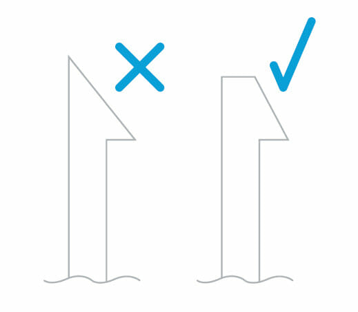
Overhang Profile
It is recommended to avoid sharp edges at the end of the snap-fit overhang, adding a small chamfer to prevent breaking during the assembly operation.
Assembly Angle (α)
As mentioned previously, the snap-fit overhang usually has a gentle chamfer to facilitate the assembly operation. The inclination of this chamfer angle (α) directly affects the mating force (P). If the angle (α) is reduced, the mating force (P) will also reduce. The
recommended assembly angle value should be between 35º and 40º.

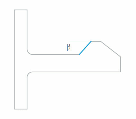
Disassembly Angle (β)
The way the overhang is designed determines whether the snap-fit can be disassembled and reassembled several times. The disassembly angle (β) affects the ease of joint disassembly. For example, a 90º angle (β) can never be disassembled. However,
a snap-fit with a disassembly angle (β) equal to the assembly angle (α) will need the same mating force (P) for both operations.
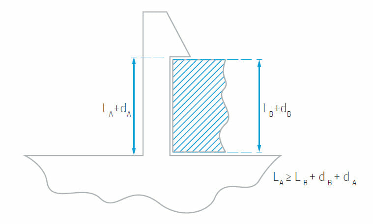
Tolerances Between Parts
When designing a snap-fit, there must be a gap between the protruding feature and the groove to ensure a proper performance, even including the worst tolerance case as shown in the following figure: