
Dowel holes are commonly used to positively align two components together during assembly and then to help keep them aligned during use. They can also help to take heavy loads off of fasteners holding the assembled parts together. It is common for 2 dowel holes to be used per part, using more holes then this is not necessary and will generally over constrain the parts being assembled causing them to go together difficultly if at all. Typically dowel holes are made using precision machining equipment like Mills or Drill Presses and due to this can be placed in a desired location very accurately and also sized to be either a press fit or a slip fit.
When being used on parts that will be 3D Printed its important to understand that the printed parts will not have the same level of accuracy as that of parts that are machined (for more detailed on printed part accuracy please see our page on the topic). This means that it is important to understand how to design around this limitation and still get all the benefits of using dowels in your assembly. There are a few general rules of thumb that our inhouse engineering department has developed over the years that make using 3D Printed dowel holes easy and successful:
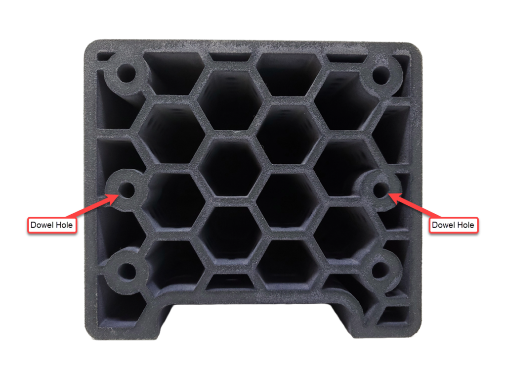
Rule #1: If your dowel holes will be CLOSER then 4″ to each other then you can use 2 true dowel holes, we recommend setting them to a press fit diameter as the printers USUALY print a bit big and if they end up to tight they can be opened up with a reamer to dial in a perfect fit.
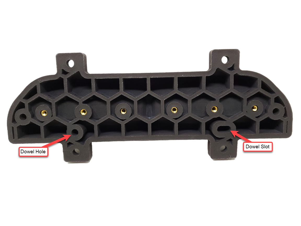
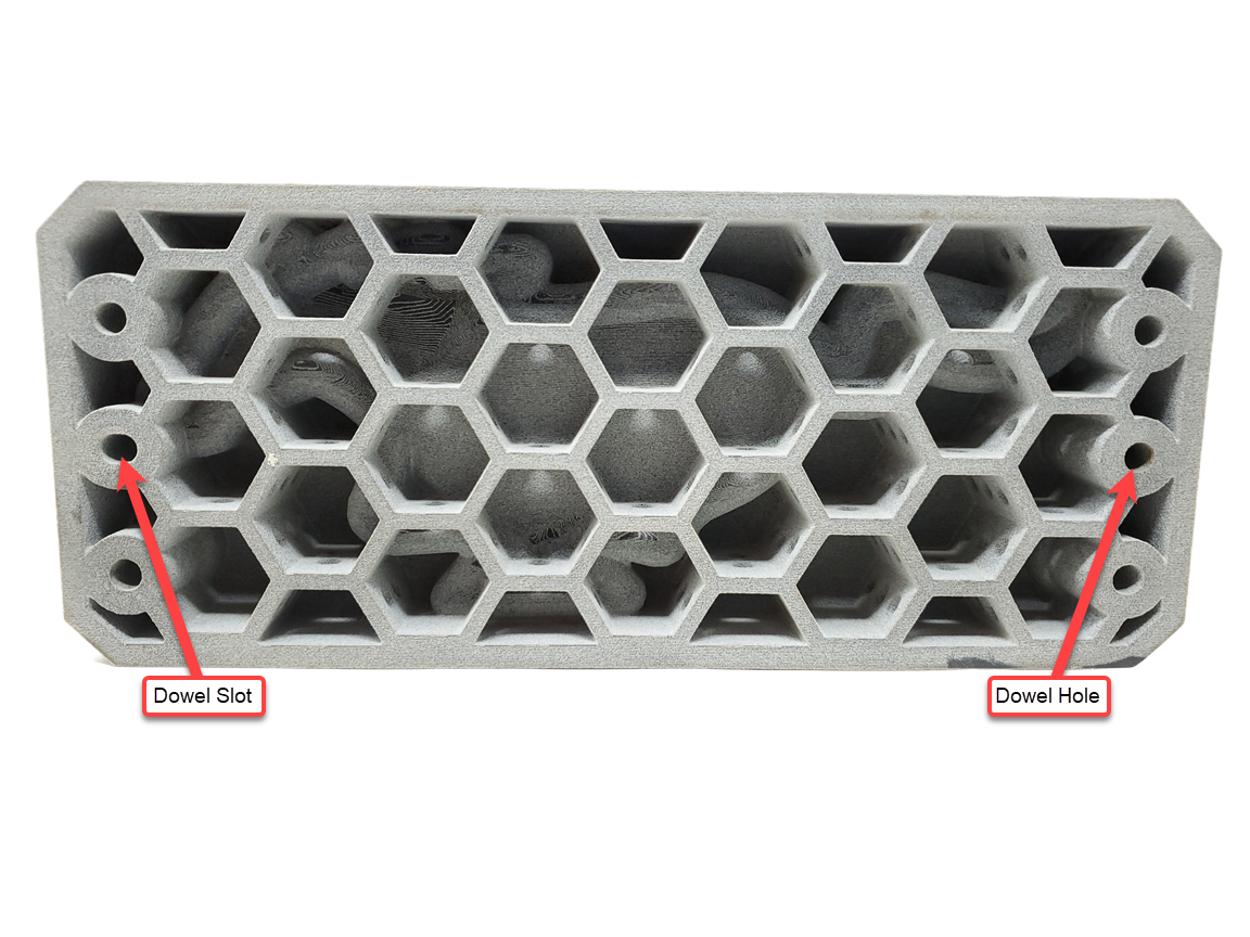
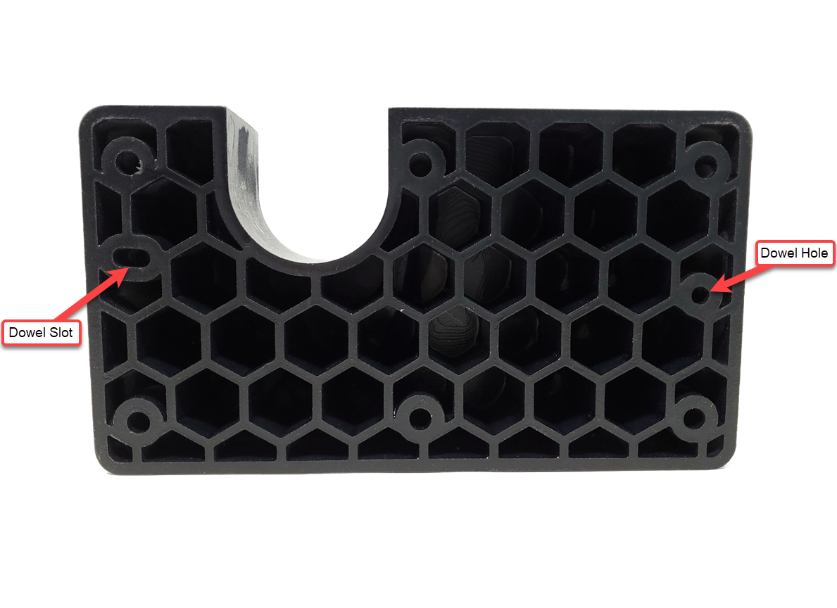
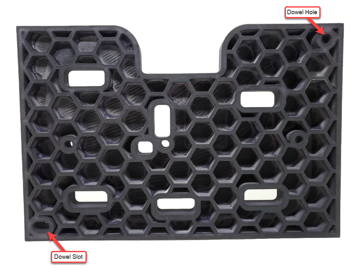
Rule #2: When you have a larger part that will have dowel holes further then 4″ apart then one of them should be turned into a dowel slot. The slot will allow for the natural inaccuracy of the printer but will still act as a positively locating feature so that the dowel system will work. If you were to use two round dowel holes in this situation there is a strong likelihood that when you went to assemble the parts the dowl pins would bind on the dowel holes in the opposite part during assembly and may break on the 3D printed parts due to misalignment.
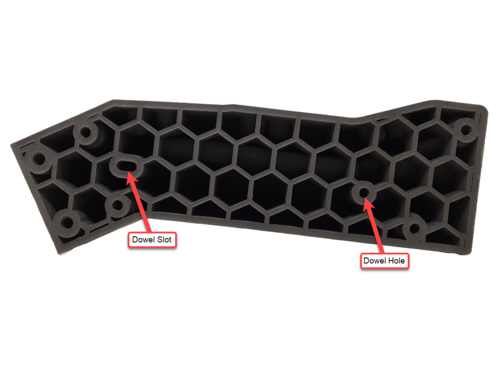
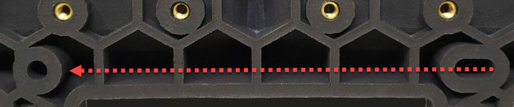
Rule #3: Make sure to point your dowel slot in the direction of its corresponding dowel hole on the other side of the part, this ensures that the slot will allow for misalignment during assembly as intended.
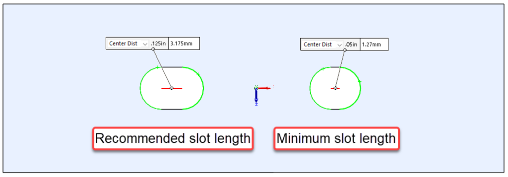
Rule #4: Your slot should be at a minimum of .125″ long, but if necessary can be as short as .05″.
Rule #5: If you need your dowel feature to be exactly on size (press fit, slip fit) undersize them by .025″ and plan on reaming them after printing. 3D printers do not currently have the accuracy needed to print dowel holes with these exact fits as required by some applications. Please keep in mind that not all 3DP material’s are machinable after printing so please reach out to our sales engineers to double check that the material you are getting your parts printed in is compatible with secondary machining.
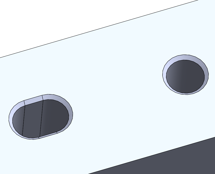
Bonus Tip: With 3D Printing complexity on your parts is FREE so adding features like chamfers to your dowel holes will not add cost and can help with aligning dowel holes with their corresponding dowel pins.