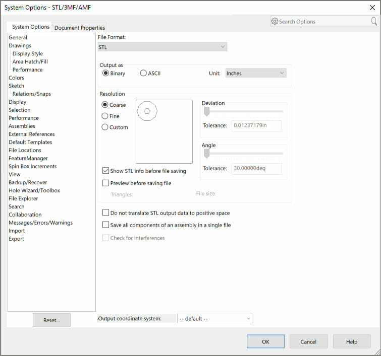
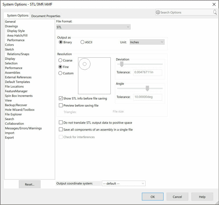
Our sales engineer, Paul DeWys, gave this presentation on Part Design for 3D Printing at 3DExperience World / Solidworks World 2020. Through the use of example parts he covers how to optimize your 3D CAD design for both prototyping and mass manufacturing on 3D Printing Equipment.
Part Design for 3D Printing Tips & Tricks:
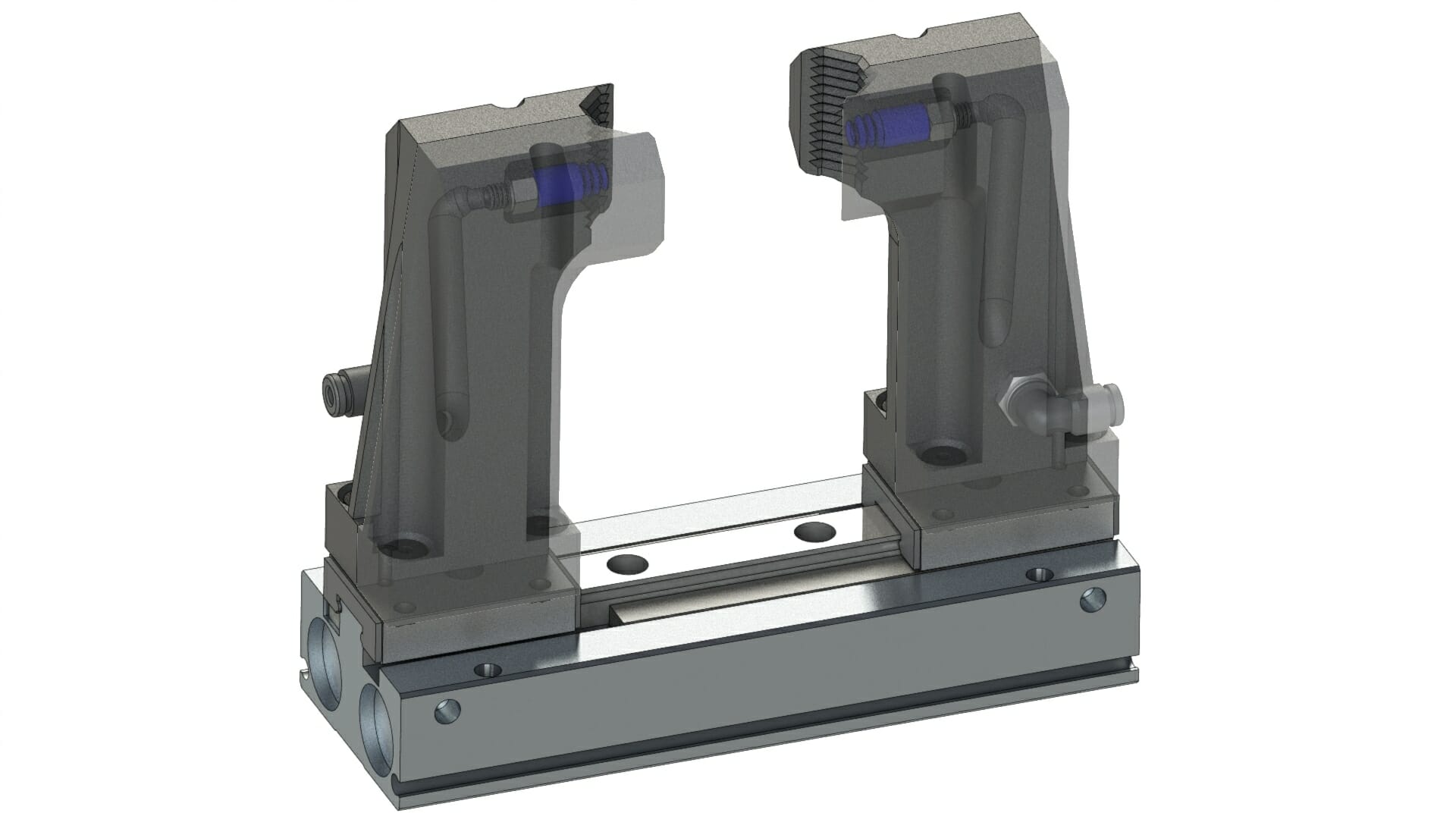
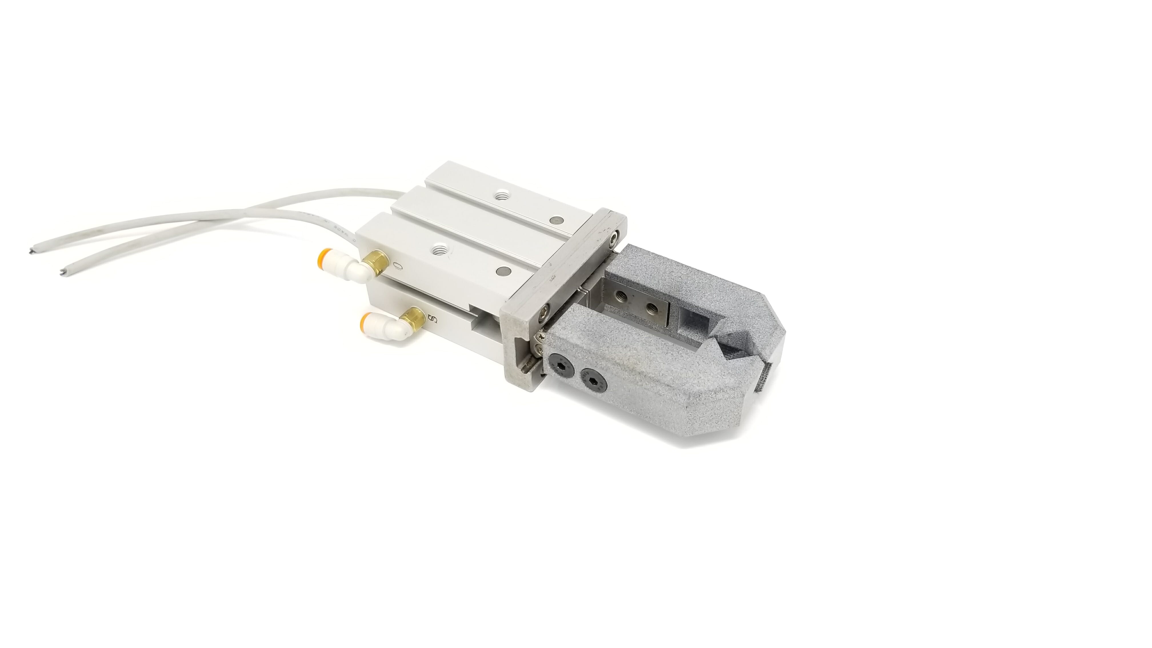
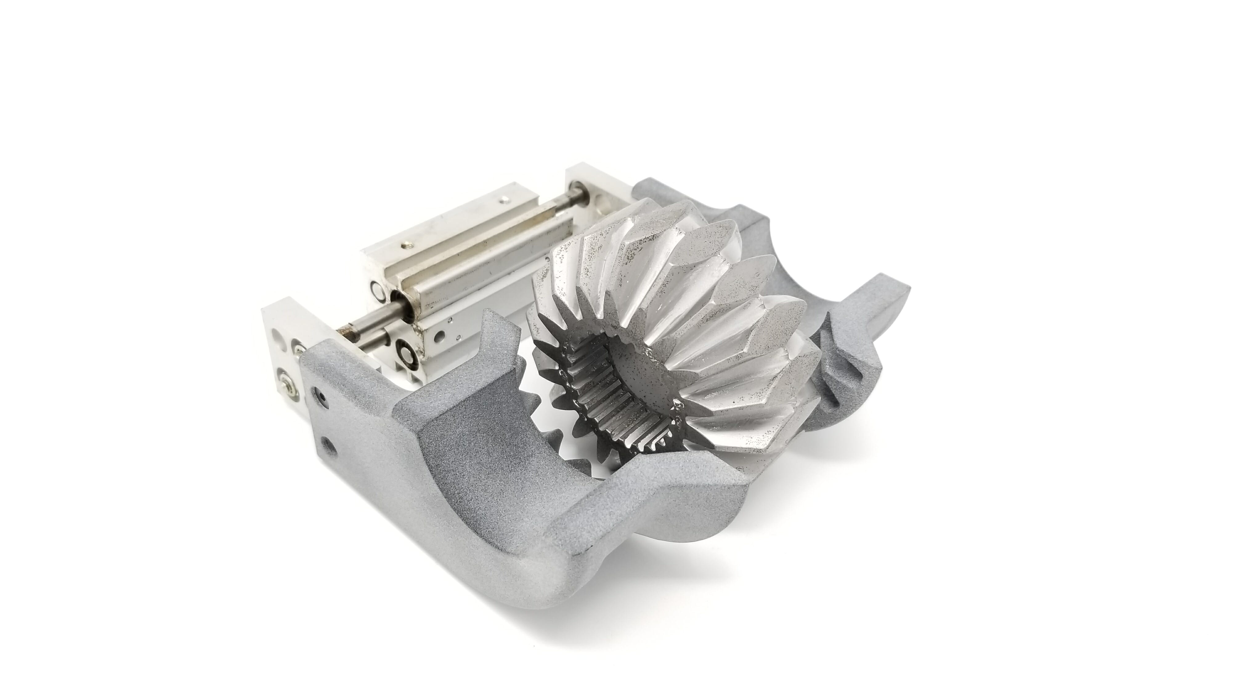
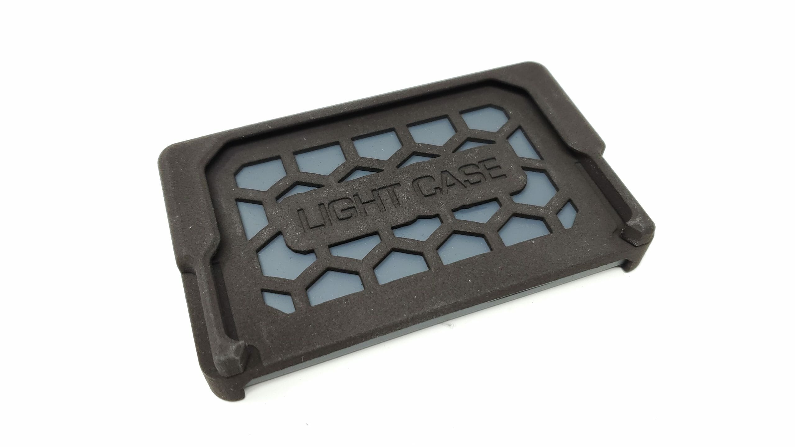
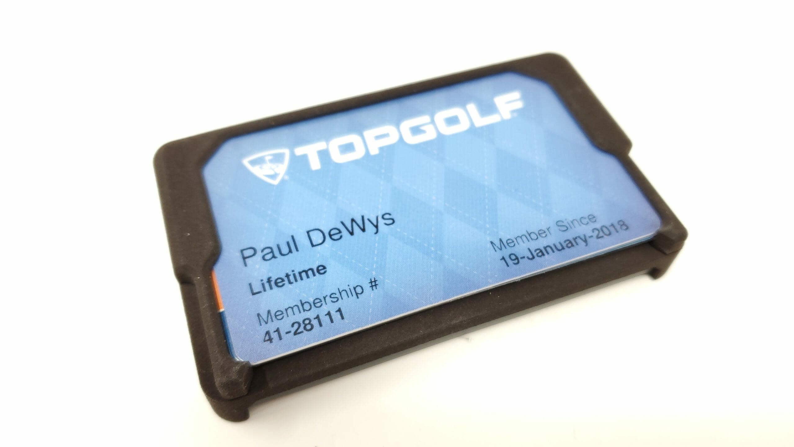
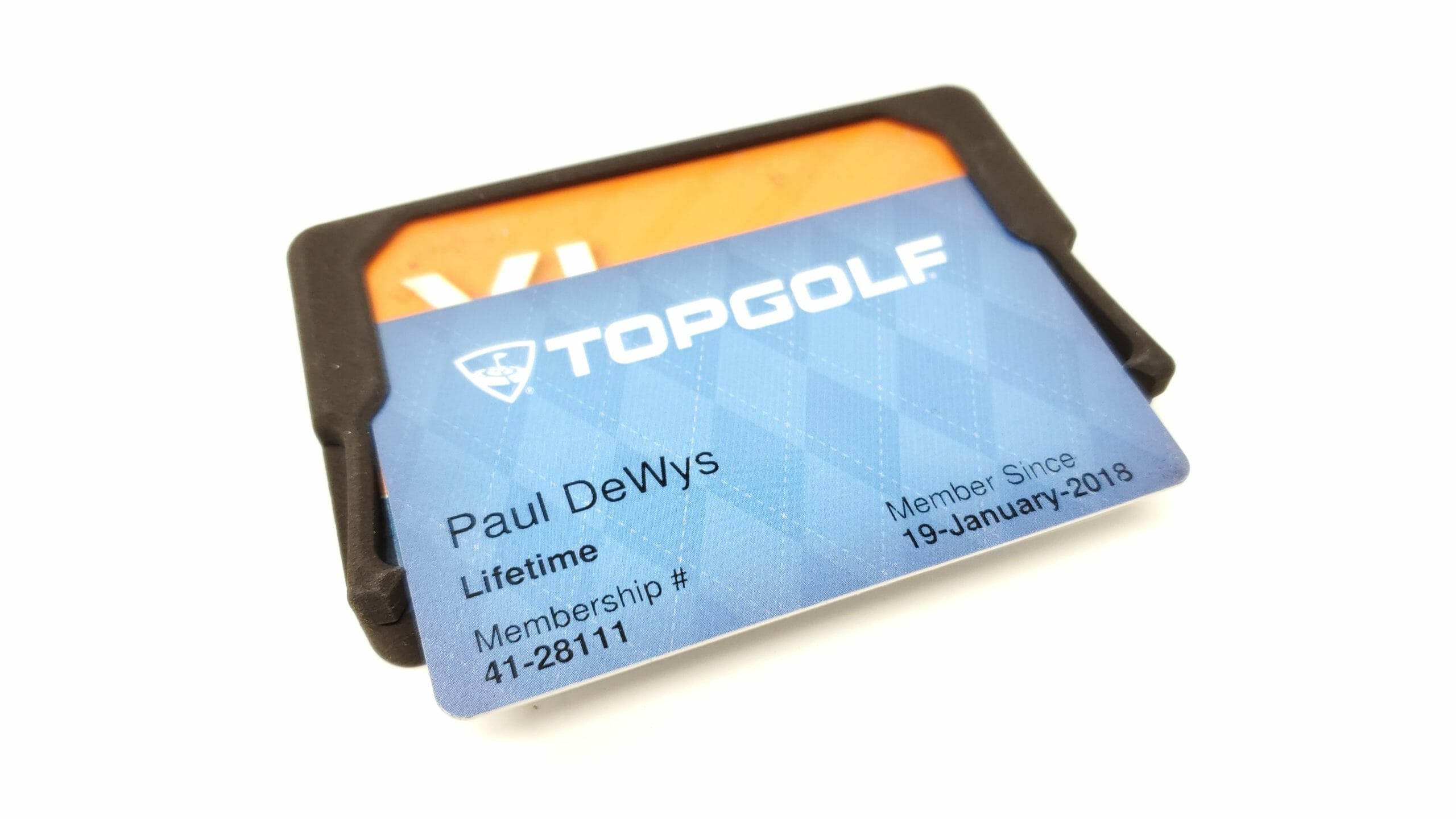
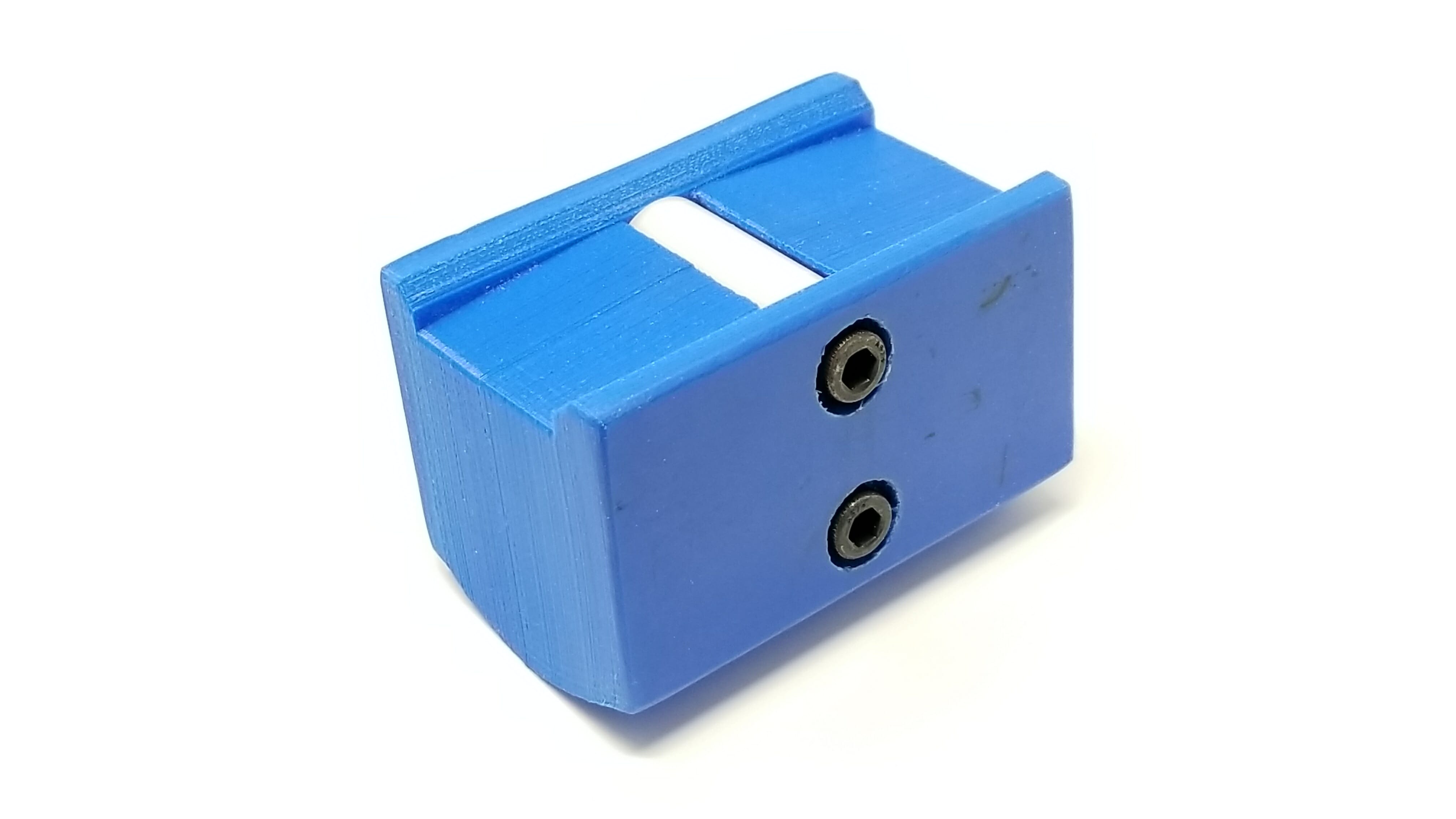
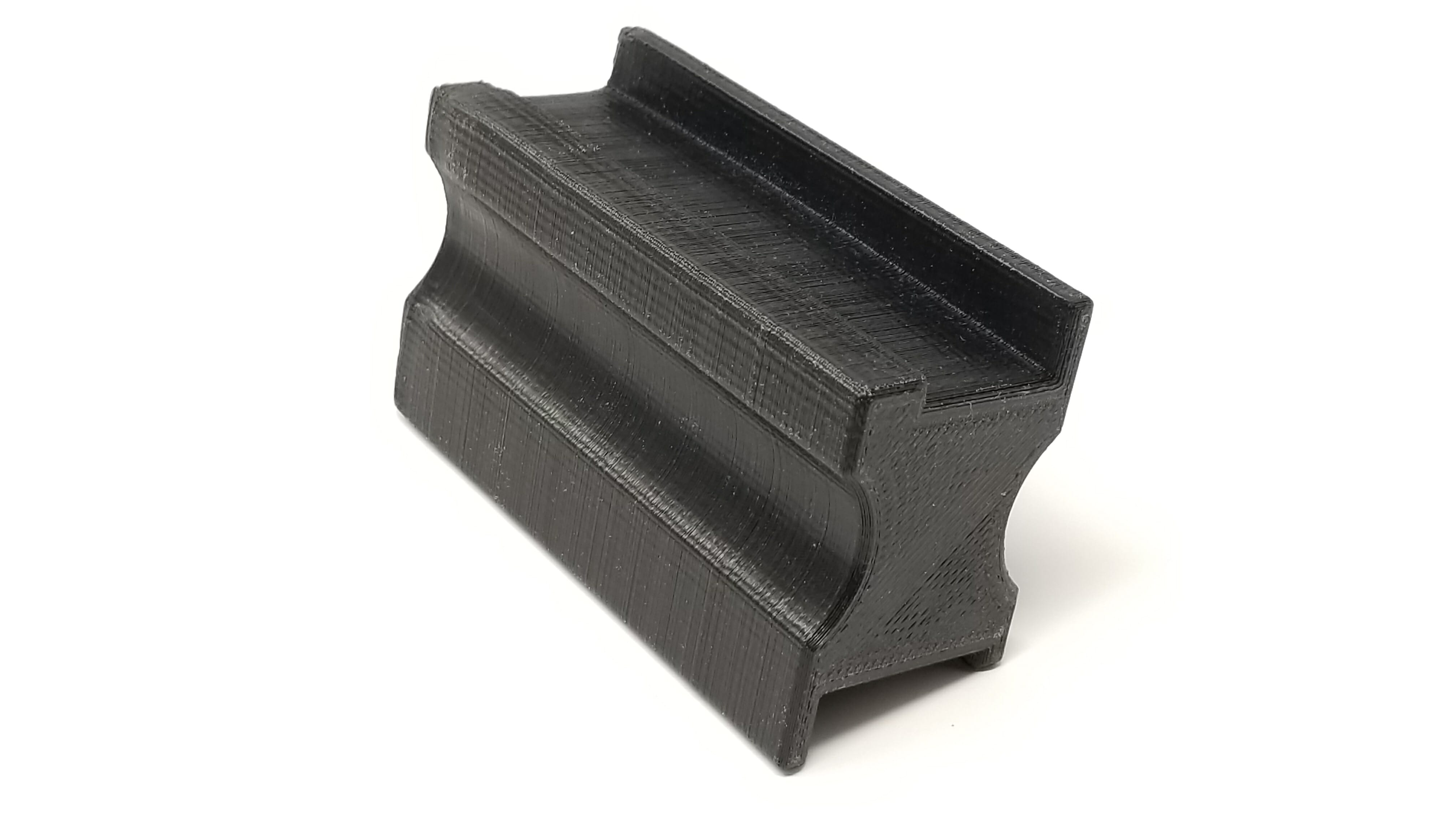
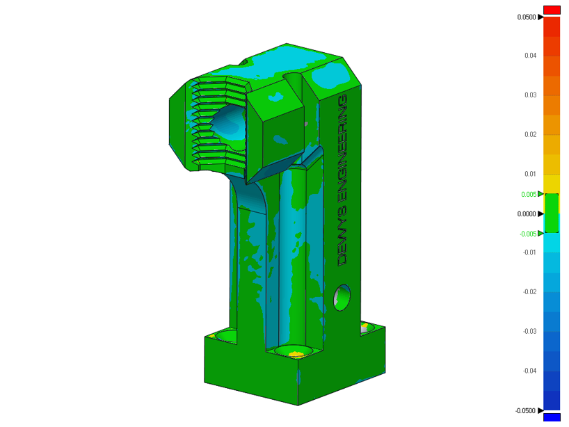
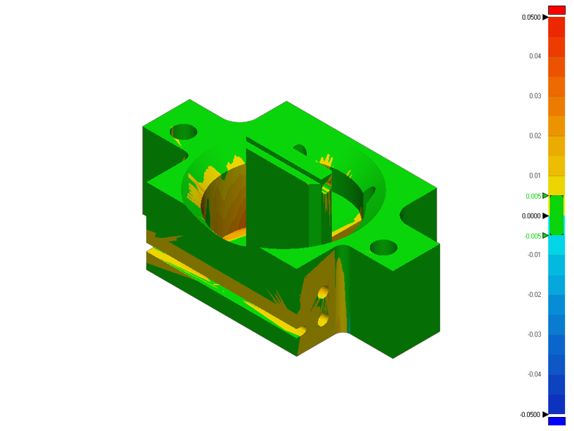
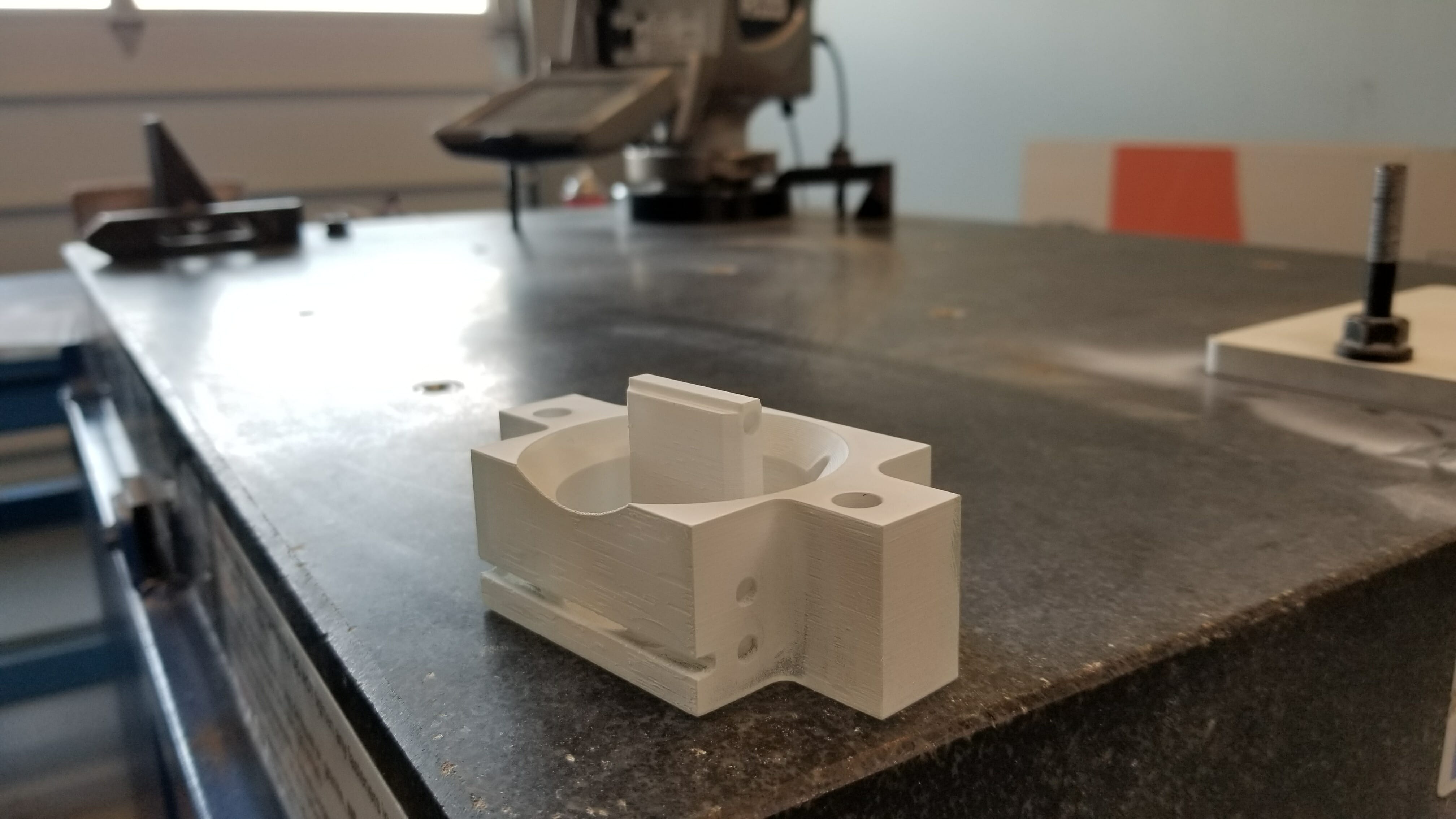
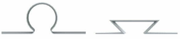
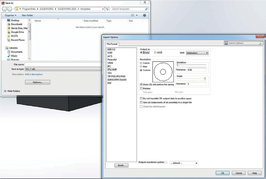
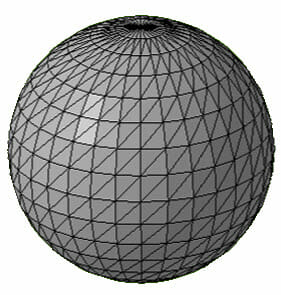
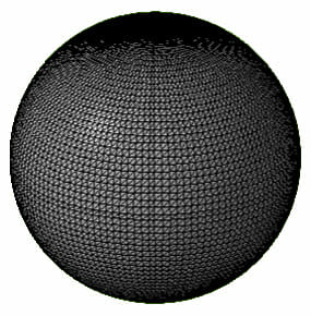
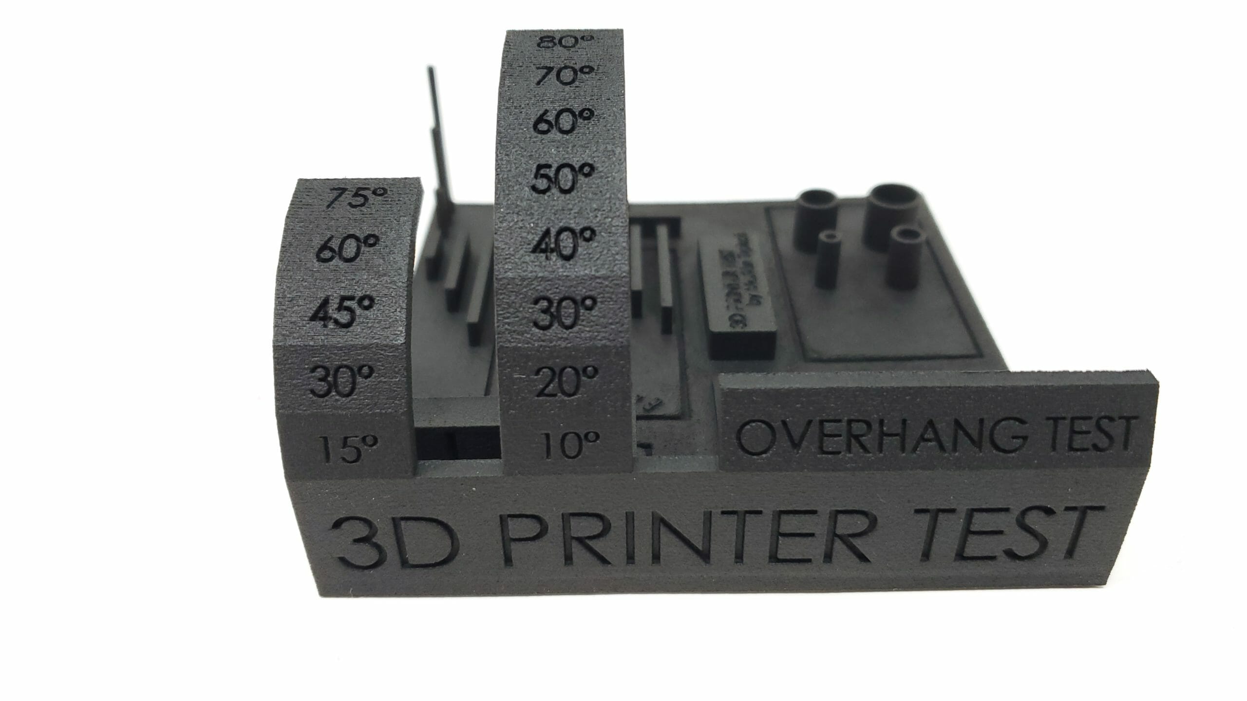
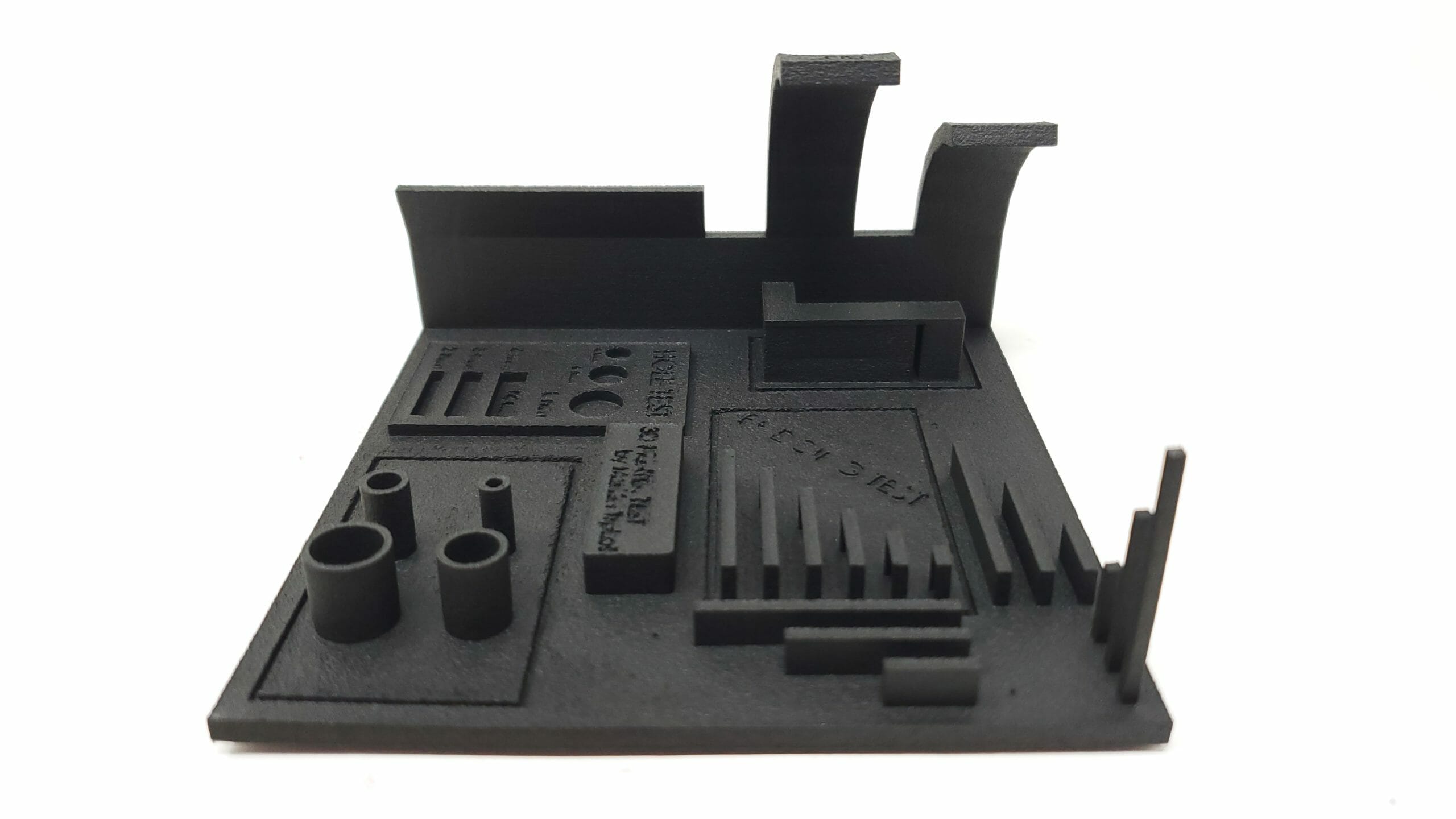
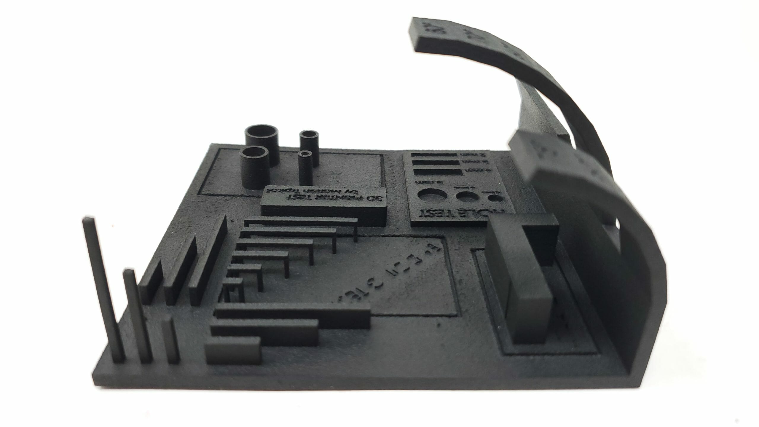
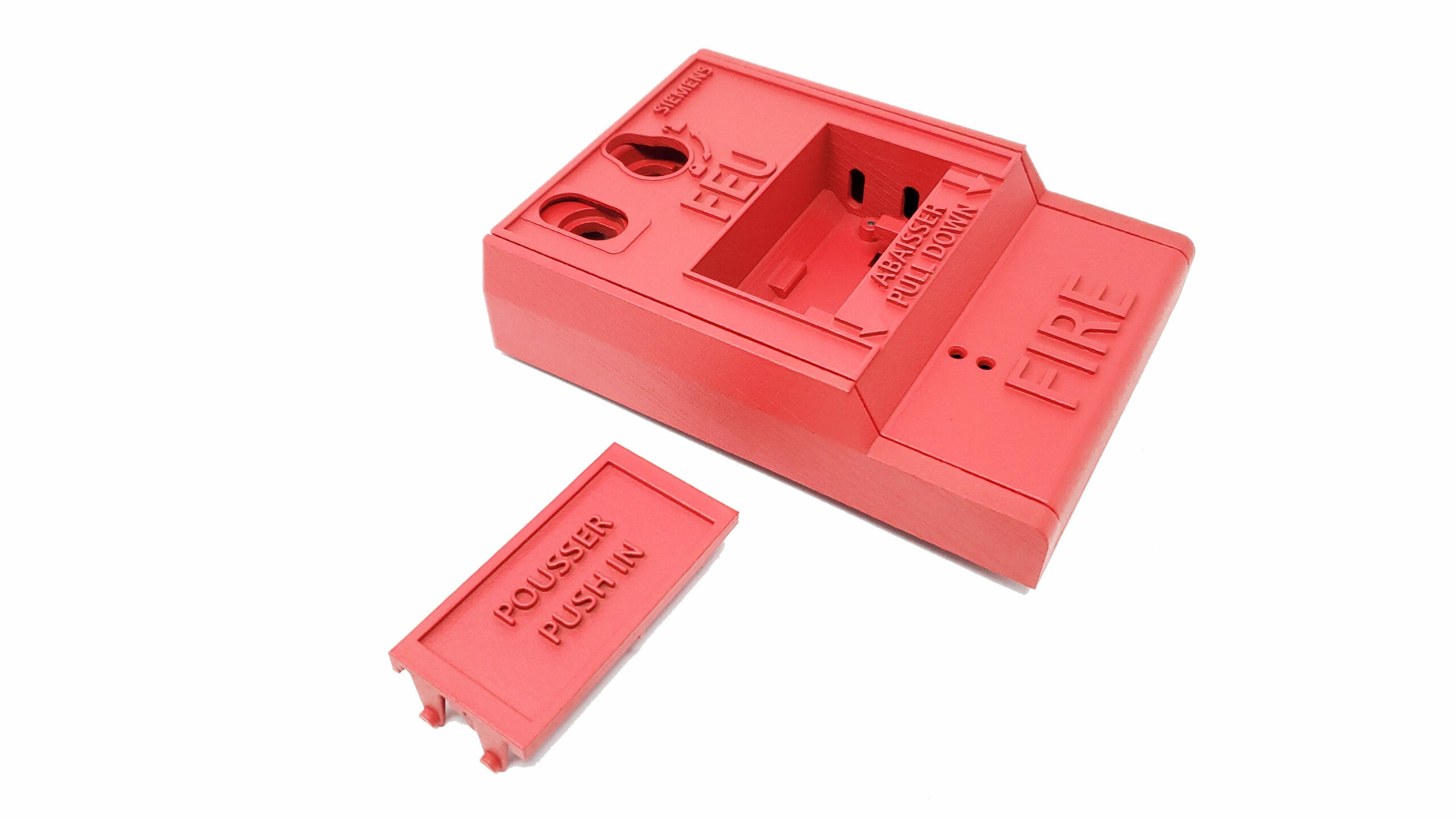
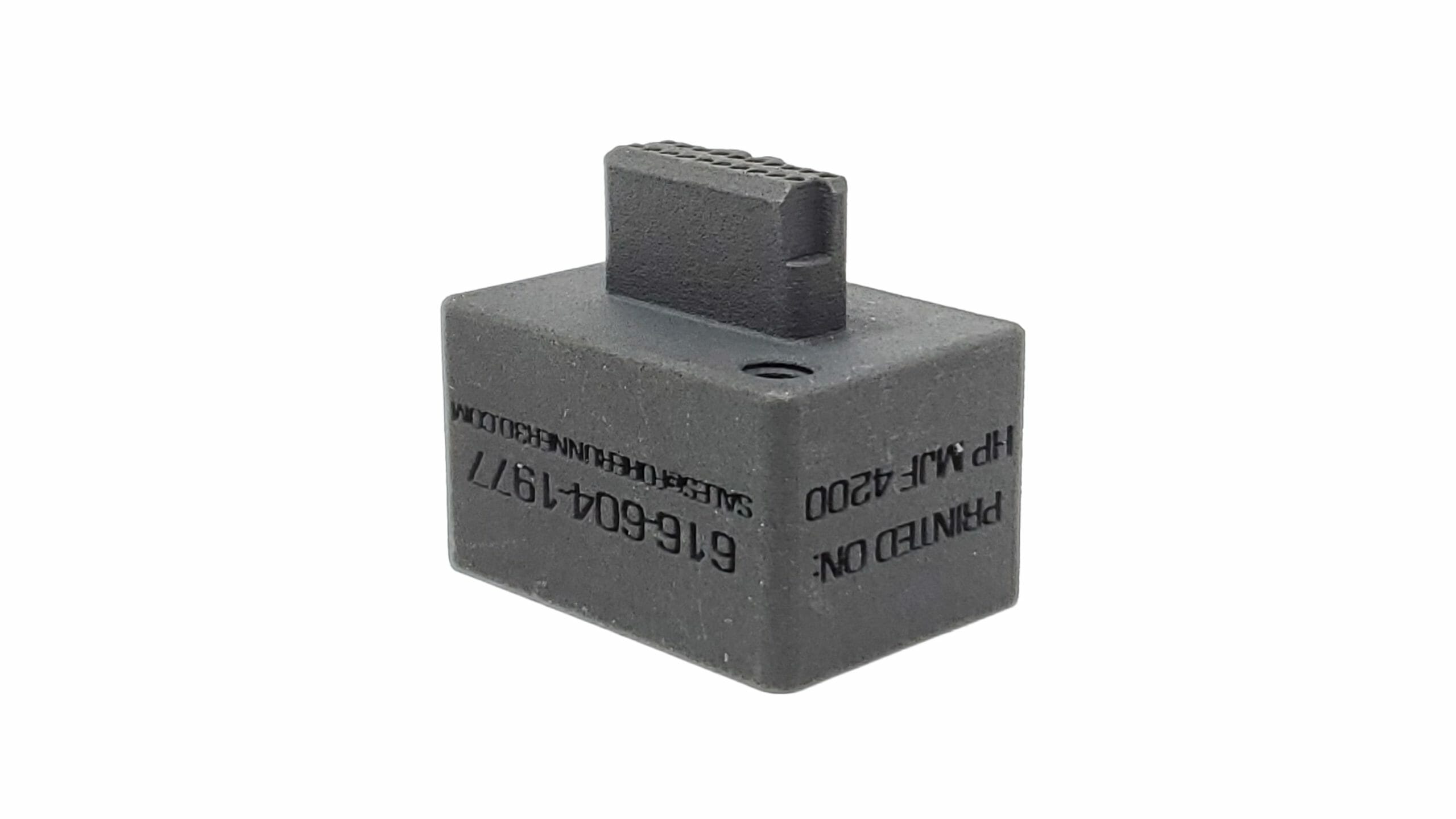
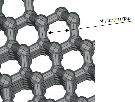
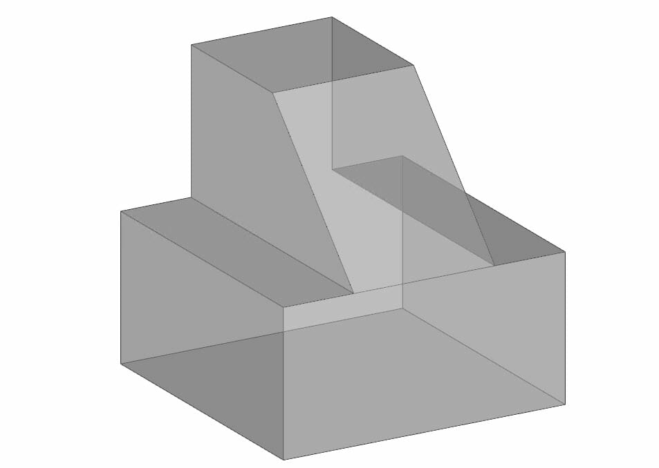
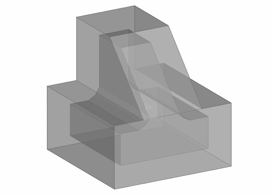
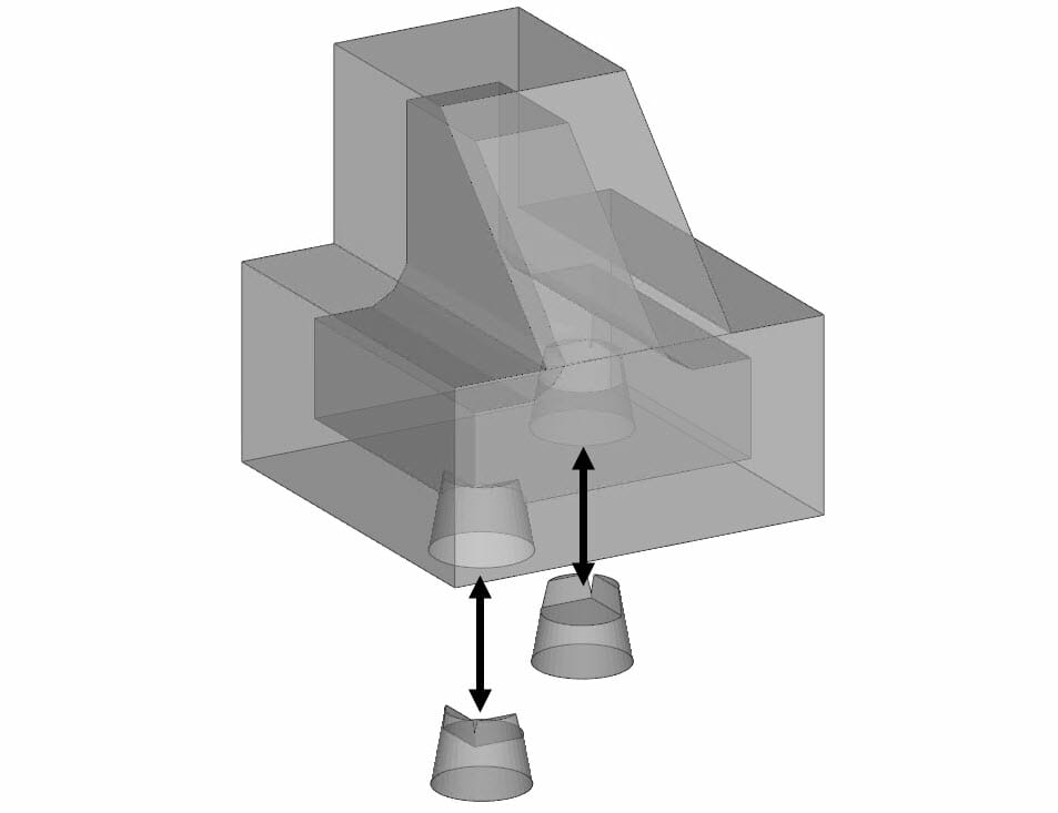
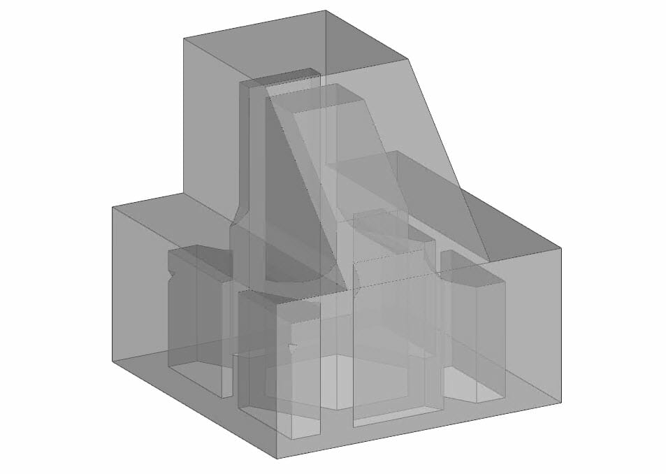
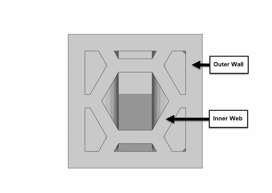
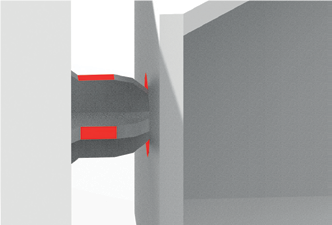
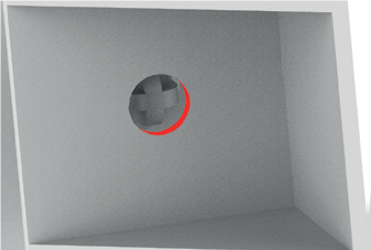
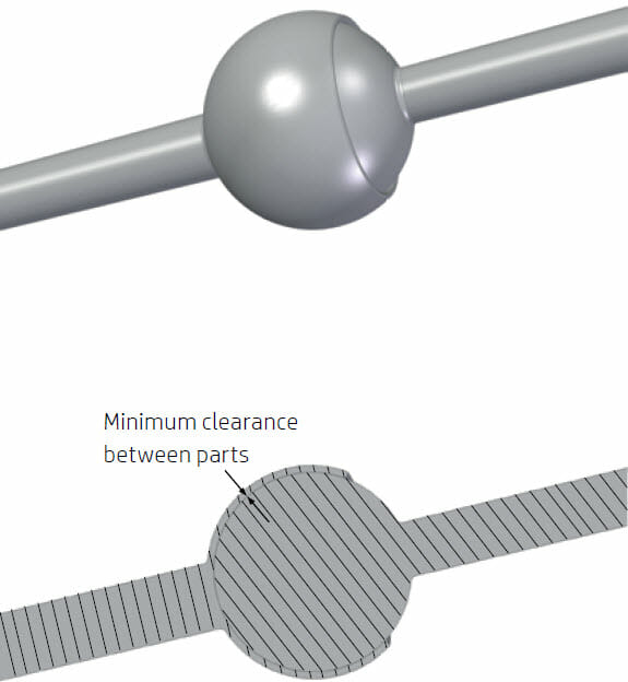
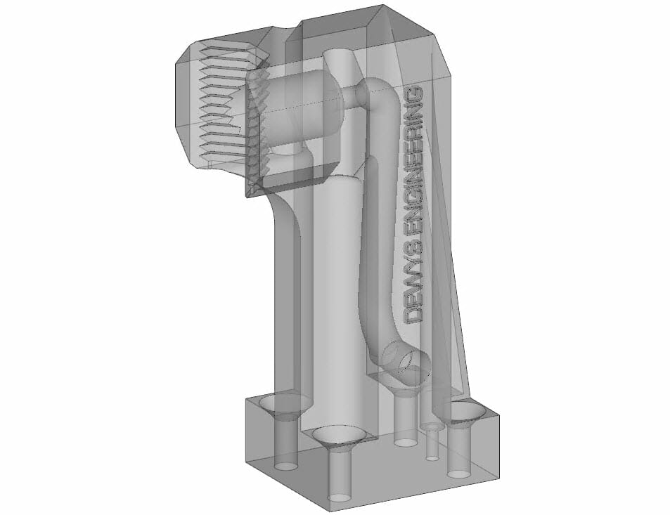
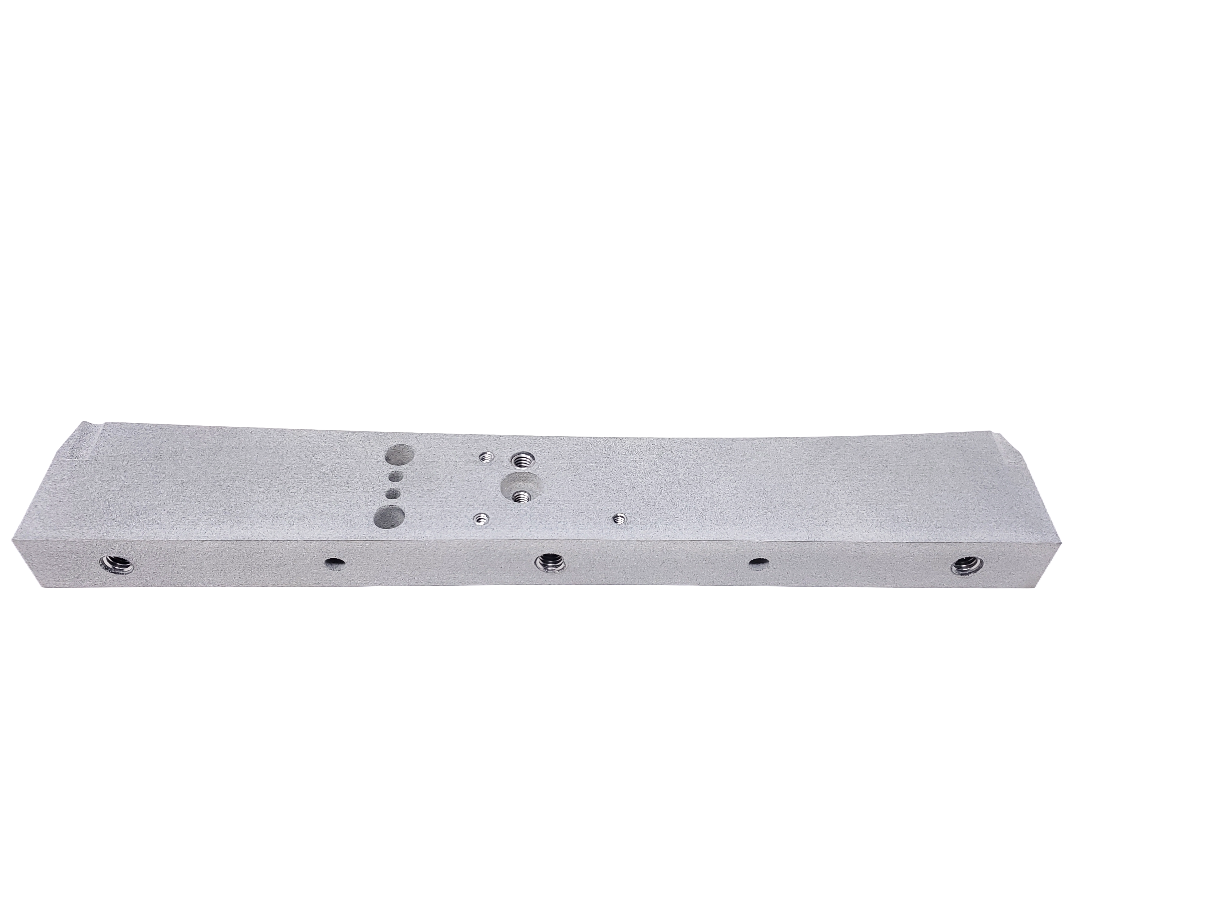
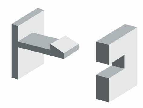
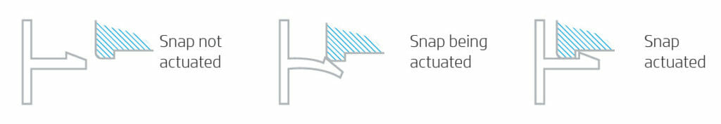
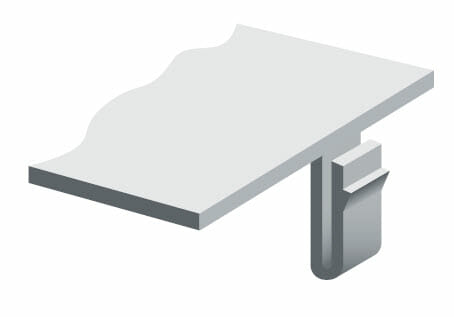
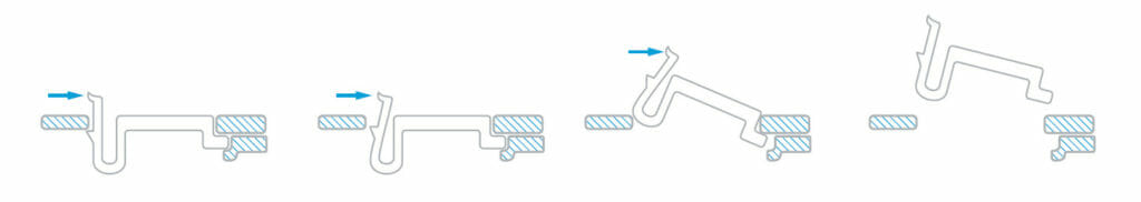
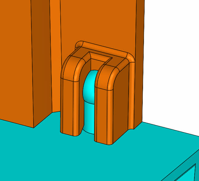
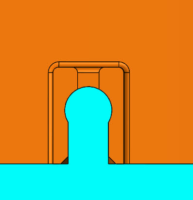
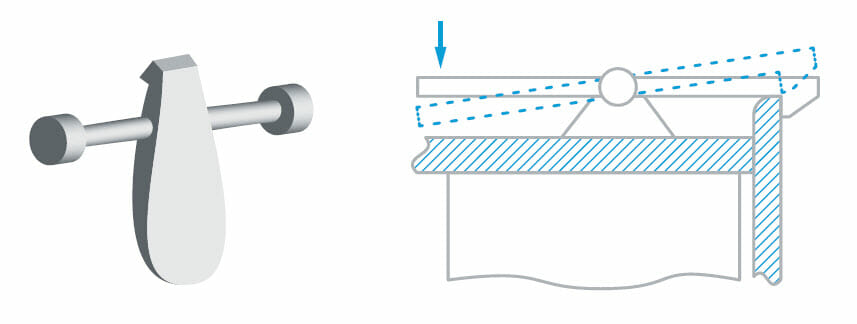
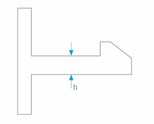
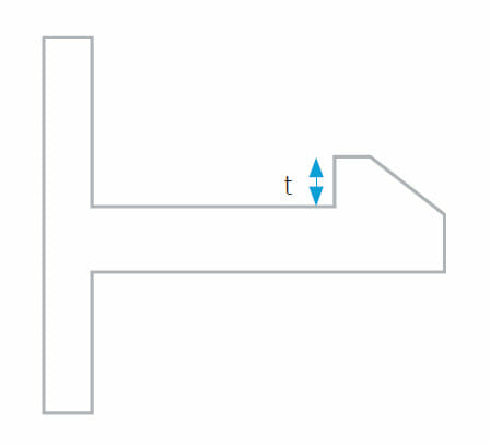
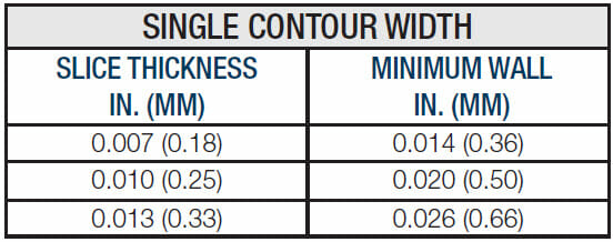
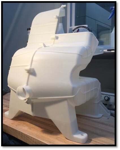
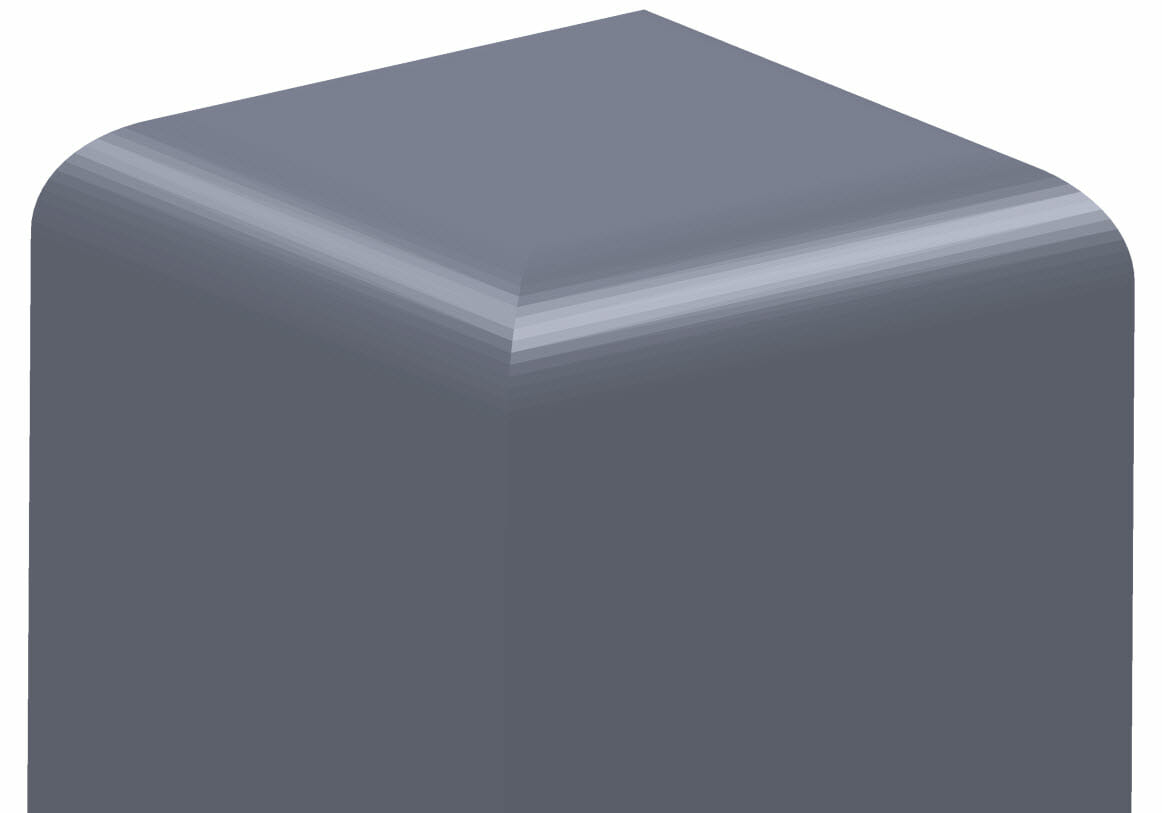
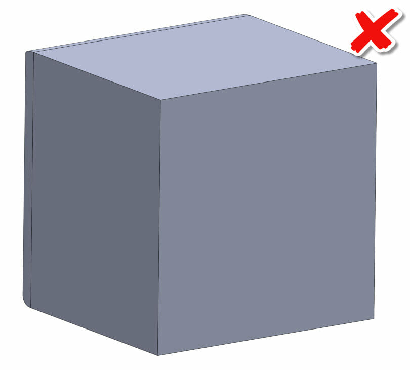
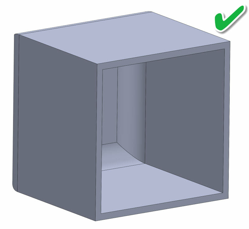
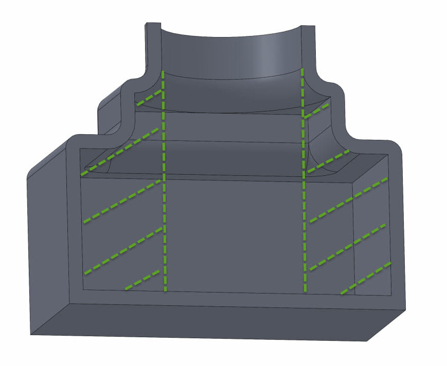
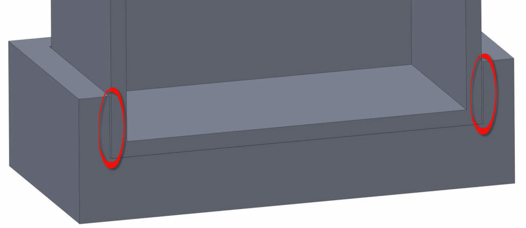
Transcript of this videos audio:My name is Paul DeWys. I own DeWys Engineering and Forerunner 3D printing. We’re located in Western Michigan, by city of the Grand Rapids is where we’re by. A little bit of background about myself and the companies. In 2009, I started the engineering portion of our business out of my college dorm room, pretty much. I was working for tool and die company and saw an opportunity to get hired to work remote from school. They hired me and the first thing I did was went out and bought a seat of CATIA, I know, and ran CATIA for that first year and then very quickly bought a seat of SOLIDWORKS, and from there, transitioned into doing almost probably at this point, our firm probably does 90% of our work in SOLIDWORKS. From 2009 to 2016, myself and a team of engineers, we grew DeWys Engineering. Today, we have customers in automotive, aerospace, a lot of automated equipment, agriculture, foundry, furniture and some new product development sprinkled in there for good measure, so pretty diversified, mixed in what we do. In that 2009 to 2016 timeframe, I was doing a lot of product development for a company. We were making cellphone cases that had tasers built into them, of all things. That required a lot of 3D printing. I found a service bureau the next city over from us and started sending all of our work over to them.Being that I’m a sales guy, I like to talk, I would go over there and pick up parts from the guy who owned it and he was a sales guy, he liked to talk, so we’d go and just talk for an hour or two every time I’d pick up parts. Over the course of six months, found out that he didn’t really have a succession plan for his business or anything like that. He was just getting close to retirement and didn’t really know what he wanted to do. Just offhand, one day, I just said to him, “Ross, when you’re ready to sell this business, you should give me a call. I’ll buy it from you.” He goes, “Well, maybe I will,” and I said, “Okay.” Then two years went by and I completely forgot about that conversation, and then one Tuesday morning in 2016, I get a phone call and it’s, “Oh, it’s Ross Gates. I’m done. I’m selling it. Do you want it?” I’m like, “Hello, Ross. Sure, I’d love to buy your business.” I hang up the phone, and then, I google, “How to buy a business,” because that was pretty much where I was at. Thankfully, Google, just like in most cases, had lots of answers and advice. By the middle of summer 2016, I bought the assets of that 3D printing company, which at that point, were two SLA machines and moved them over to where DeWys is at and started up Forerunner 3D printing. That’s kind of the quick and dirty short version of how I got into the 3D printing business and where we came from before that. Shortly after getting into the 3D printing business, it became clear that end-use parts, not just prototype, were possible with these machines, but you needed to design for them, just like you would for injection molding or stamping or sheet metal fabrication. Generally when I say that, the first thing that people will respond to is, “But I thought, with 3D printing, you had unlimited design freedom?” You do. You absolutely have unlimited design freedom, but just like with any other process, if you optimize your design for 3D printing, there’s lots of cool unlocks that you can get from doing that. One of them is isotropically stronger parts. What does that mean? Well, typically, 3D printer parts are strong in X and Y but weak in the Z direction, weak with the layers. Well, there’s ways around that. You can design around that to make your parts isotropic, where you have strength and all the directions that you need and you might sacrifice strength in a direction where it doesn’t matter. Less post processing time. Anyone here who’s ever used anything from a $500 MakerBot FDM machine, all the way up to $500,000 3D Systems SLA, everyone knows when you take that part off the build platform, half the work is done. Now, you got to take all the support off of it. You can have tons and tons of time and frustration and scrap parts from dealing with support. There’s ways you can design around that. You can design it to have no support or you can design it to have minimal, easy to handle support. That’s another thing to think about when you’re looking at additive. Then added functionality and unique features. 3D printing allows for things like integrated springs, printing assemblies as a single part, trap components, non-machinable, non-injection moldable and non-stampable features. Because you do have that crazy freedom that 3D printing affords you, you can do some really wild stuff. That’s what I’m going to show you here today.Then lastly lower cost. Anyone who’s ever dealt with 3D printing over the years, especially if you don’t own the equipment yourself, if you’re coming to a service bureau or an additive manufacturer like us, will know 3D printing can get eye-wateringly expensive in a very, very short amount of time, depending on what you’re trying to do. Well, again, if you design your part with 3D printing in mind, there’s ways to get around that. There’s ways to take apart that might cost $1,000 per piece and drop that down to $250 per piece by getting a little creative with how you design it. The following examples are going to be parts that were either specifically designed for 3D printing or parts that we took in from customers and ran through our engineering department to redesign them to be 3D printed. I’ll just throw this out there, guys, like I’m just going to crank through this. If you have questions, raise your hand, but if I’m not looking at you, feel free to just be like, “Hey, Paul, I have a question,” or, “Hey, I have a question.” Otherwise, we’re just going to keep cranking right to the end. First thing I like to do in each section, I like to do a little technology overview just because there might be people in the room that aren’t familiar with what the equipment I’m talking about. I’m going to summarize the three piece of equipment we’re going to talk with a little video here at the frontend of each one. The first technology we’re going to talk about is SLA, stereolithography. This is the first 3D printing technology that was brought to market. It was brought to market in 1990. Essentially, you’re using a UV curable resin down in that vat and you’re using a UV laser. Wherever that laser touches the top surface of that vat, it’s going to cure between a 1 to 10 thou thick layer of that material, depending on your settings. Layer by layer, that laser hardens up each layer material, and then, you recoat, harden up the next layer. Recoat, harden up the next layer. This technology has been around for a very, very long time in the world of 3D printing. There’s still a lot of great applications for it. It is a little bit limited by some of the material science and stuff like that. A lot of people use it just for prototyping, especially if you’re prototyping big plastic enclosures. You want to check stamps, you want to check screw bosses, things like that, but I have an application where we actually used SLA for an end-use part. Like I mentioned, about half of what my engineering company does is automate the equipment design. We had a customer that came to us with this part or a machine that required this part. The challenge, design a block that could route both high pressure air for blow off and a strong vacuum to remove blown off dust in one part. We used a computational fluid dynamics, CFD inside of SOLIDWORKS and that analysis had guided the designer to angle the high-pressure air holes in a very awkward way for manufacturing. This area right here on the top, we’ll get a section view of that in a second, it’d be very difficult for traditional machining to put those holes in there, if not impossible. The block also had many internal air and vacuum channels that would have required many setups in the mill. Also, we would have had to gun drill this block and actually turn it into an assembly, so there would have been a lot of places in there. We have sharp corners where eddies could have formed and you could wind up with a lot of materials trapped inside the block not easily cleanable. Due to all this, we designed it specifically to be 3D printed in so most watershed on an SLA 500. Then because we needed it to stand up to a shop for environment, I guess that SLA is aren’t known for their strength. We actually encased it in a stainless steel block. The SLA never came in contact with the strip media that was rolling through it that we’re blowing that dust off of and then vacuuming it into this block. Stainless steel took all the wear. The block was just really for air and vacuum management. All right, we’ve got a couple different views of the block here. 3D printing allowed the high pressure air holes to be arrayed at very specific angles and locations called out in the CFD. You can see here. Actually, this is even a better view right here. They’re arrayed across the top to fan out and hit the entire bottom of the substrate that we’re blowing off. Again to do that in traditional machining would have been extremely difficult. The four vacuum chambers had to or had the ability to be tapered to a very specific mouth size to do optimum draw based off of analysis and everything like that. You can see these purple chambers right there, those are actually vacuum chambers. You’ve got high pressure air in the middle, you’ve got vacuum to either side of it. Again, we could get very, very exact and how we want those vacuum chambers to be created. After placing all the HPA ports and vacuum chambers in the block, we then plumbed it. We have all of our air and vacuum coming in through the bottom. Once we had those chambers in place, we just routed all of the supply lines through unused areas of the block completely. Wherever we wanted to put it, we could put it which is really handy. One of the things that is kind of important to point out with this one is thinking ahead when you’re designing about having a trapped volume. We can’t get support out of these internal chambers after we print it. You want to think ahead and use things like high angles. That’s a 60-degree angle for the roof of those vacuum chambers. Anything over 45 degrees in 3D printing is self-supporting. It doesn’t need support. That means we don’t have to worry about anything being in those chambers. SLA is a liquid process. Whatever liquid resin is trapped in there when we’re done, we just hit it with compressed air, it blows it right out and you’re left with an empty clean vacuum chamber. Same with the array of holes across the top, you’ll see that that’s an arch. Think back to basic engineering when you’re in school, you build an arch. It’s self-supporting. Same thing here. We don’t have to have a bunch of support inside of that chamber that we have to figure out how to get out of afterwards. Then, all of our passageways, these purple and teal passageways, they’re all circular. Don’t make it square. Don’t put a flat top. You have to have support in there. It’s that kind of stuff that if you think ahead in your design phase about how you’re doing the internal structure, you don’t have any support to deal with, so you just completely unlock a whole new design that you can do with 3D printing that you couldn’t do with any other process. Let’s see here. Then lastly, you notice this has a nice flat bottom on it. The part has a nice flat bottom. Very, very easy to build support, up off of the build platform, build support up to that bottom. Rip it off the build platform when you’re done printing it 30 seconds with a piece of sandpaper and that is all the postprocessing that this part needed. I’ll tell you this as someone that owns a 3D printing company, yes, the machines are expensive, but manpower is right up there too. I have to bill out $60 an hour for a modelmaker. If I have to have a modelmaker sit here and sand this thing for four or five hours, you can do the math. You just increased your part price by that much per part. Anything you can do to reduce sanding or reduce bench time is going to go right back into your pocket. All right. Oh, one last thing, a SOLIDWORKS tip for you guys, Draft Analysis. I’m sure anyone who’s done anything with maybe castings or with injection molding, Draft Analysis is used for parting line analysis and things like that. Well, you can also use it in situations like this where you go, “Hey, what areas inside of my block are violating that 45 degree rule or violating that arch rule?” You can use Draft Analysis to very quickly select the bottom plane of your part, turn it on, and boom, everything’s green or everything’s red. You know exactly what your problem areas are. Draft analysis is a really handy SOLIDWORKS tool for evaluating this stuff. All right. Take a quick sip here. Onto the next technology. This one is somewhat newer. It’s HP MJF. If anyone here has ever messed around with the old 3D Systems or DTM laser sintering machines or EOS machines that use a laser to sinter powder, this is a new spin on that. There’s no lasers involved in this. This is HPS take on SLS. It’s called HP MJF, Multi-Jet Fusion. We have a print bed, and on our print bed, we’re printing this gear. We just finished a layer. We’re getting ready to start the next layer. First thing the machine does, it spreads 0.0003 of an inch thick layer of nylon powder, white nylon powder across the top of the part. Then it comes over and it coats the entire bed in one pass with fusing agent and detailing agent. Detailing agent gives you really crisp geometry, crisp sharp edges. The black fusing agent, when exposed to high-energy IR light, like it is right here, that black fusing agent absorbs all that IR light. It drives the temperature up in the blackened region of the print bed and it actually melts and sinters all those nylon particles to each other and to the layer below it, but that detailing agent prevents it from sintering to any of the white powder around it. You think about it, you got a black car and a white car in a blacktop parking lot in the summer, black cars are always going to be way hotter than when you get into the white car. We have a white powder bed and we have a black part region. The black area gets way hotter. The white powder around it reflects all that IR energy and does not melt. The advantage to this over SLS really comes down to speed. You can run this machine way faster than you can run an SLS. That’s why this is one of our favorite machines for low volume manufacturing. The example here, ratchet safety cover, the challenge take an existing safety cover for a high-speed ratchet assembly tool and redesign it from machine Delrin plastic to a part that is 3D printed out of nylon 12. The decision to move from machining to 3D printing was driven by two factors, lead time and cost. The annual usage for this part is between three and 500 units and the diameter changes with every run. The customer could not justify an injection mold and then they were machining them for that reason. The lead times and machining costs had steadily increased for the CNC machines used to produce these over the years to the point where they just couldn’t justify it anymore. Well, they could justify it, but the owner of the company was so frustrated by it. He was open to anything that would get him away from CNC machine plastic. We were working on another machine design project for him. We came across this when we were working on it. We said, “Hey, give us an opportunity to see if we can convert this over to an HP MJF part for you printed out of nylon,” and so we did. One thing, Delrin has a little bit more … Stretchy is not the right, but it can elongate a little bit more than the nylon. Nylon is a little bit stiffer. Originally, it was a solid diameter all the way around and there’s a detent inside of there, to detent over the ratchet. When we originally printed it, we printed it solid and we went to press it together with our arbor press, the nylon part would just explode. It would just crack, whereas Delrin which stretch a little bit and so it would work just fine. What we came up with is, “Okay, well this isn’t working. Let’s petal the design,” essentially, think about petals of a flower coming open. All they needed was it to momentarily stretch and then snap back over to do that detent. With 3D printing, I’m going to say it once, I’m going to say it 1,000 times in this presentation, complexity is free. It’s size that will cost you. In this case, add these slots and there’s not like a separate setup. It’s not like it just went from a three to a four-axis part. It doesn’t matter. Complexity is free. We petaled the design and it worked great. It solved our cracking problem. The next thing was, once the customer saw the original design, they said, “Oh, this is great,” but now, we have a guy going through and literally writing in Sharpie on every single part what the size is. Would it be possible for us to actually print the size of the ratchet being held inside of it to the outside? Again, no problem. Complexity is free. We put the text. We put the size on the outside of the part and it doesn’t matter. It literally doesn’t cost them anything extra to print text in. Anytime you can add text, logos, texture, anything like that to a 3D-printed part, it’s not like machining or injection molding where, “Oh, it’s injection molding. We put a logo on the space. Now, I got to add a slide to get that part out of there.” No, it doesn’t matter. It literally doesn’t cost you anything extra to add those features to your parts. A little trick though, if you’re getting into a product where you’re going to be iterating, a whole bunch of different versions of it and you’re going to be constantly changing the text on the outside of the part, you can take and you can link the text inside the SOLIDWORKS model in the sketch. You can link it to a field in your property tab manager. We use a start part. We’ve done hundreds of different sizes of these. We have a start part that we start with every single time and it’s got all of this already built into it. When we pop open our property tab manager, there’s literally a field that just says notes and we type the size in there. When we hit rebuild on the part, it literally propagates it right on the side of the part. Afterwards if anyone wants a copy of this PowerPoint, feel free to come up and I’ll give you the PowerPoint. It literally steps you through exactly how it works up here, but for sake of time, I’m going to just keep it moving. This is a great way to do mass text customization and not be in there editing sketches every single part. It’s very easy to do and quick. Let’s see here. Another example here. Example, end-of-arm gripper fingers. The challenge, reach into a very tight space and an injection mold and place a part for overmold. Due to the number of grippers required on the end-of-arm tool, they needed to be lightweight. The grippers also needed to house vacuum cups. There would be no room to route vacuum lines along the outside of the gripper fingers. They needed to be routed through it. This is actually one where we originally did all this like we would normally would, machined aluminum, typical grippers and things like that, but we kept having this issue where the pick and place robot would go into the mold and they would actually catch an air line on, I think it was a lifter and it would snag every just enough to make it a problem. Every 10,000 cycles, they’d snag and it would break the air line and then you’d be dropping parts and it would be mess. The customer said, “We got to figure out how to get this air line out of the way,” and we said, “Well, shoot, let’s make a 3D-printed gripper finger and we can kill a bunch of birds with one stone here. We’ll actually route the air line through the inside of the gripper finger.” Specifically, I’m talking about this one here in the center. These are just some examples of other gripper fingers we’ve done over the years. This is the SOLIDWORKS model. This actually shows you know the solid part or the part. Here it is with a section cut through, it ghosted and then here it is with a true section, so you can see the air lines that are going through there. One of the most beneficial features of 3D printing is that it can print features that are not possible or would be very expensive through traditional manufacturing which in this case would be CNC machining. Coming at this detail, having to gun drill down through it, plugs in, things like that, in this case, just do a sweep cut through there and you get your air line right inside the part. The gripper fingers need to have vacuum cups placed in them due to space constraints. We already talked about that. A tip, for any time you’re doing an internal passage through, in this case an MJF part but even like something like an SLS would be the same way, we like to keep our internal passageways at least 3/16 in diameter for depowdering purposes. I’ll touch on this again and a little bit with another example, but when we’re done printing, the part is full of powder and we have to get that powder out sometimes. Well, we’ve had customers that want us to print a 25 thou air passage going all over the place inside of a part. Well, the part gets so hot that even though you’re using detailing agent to try and keep that powder inside of there from centering, you’ll wind up with an area that got too hot and that nylon will melt inside that channel and you’ll never depowder it. You essentially have a little plug somewhere in that route. We typically say, “Print at 3/16, he bigger the better if you can, and then neck it down at the very end,” where we can go in with a brush or even a steel punch and pop that that last little section out of there, and then, you can put in your threads or you can just leave it as a nozzle or something like that. If you’re doing a powder-based machine always be thinking about like, “How am I going to get this powder out of the part? Then more importantly, am I going to wind up going too small and creating a plug inside of this path?” something to keep in mind for powder-based machines. In this application, another thing, was adding texture. We had a problem with this dropping part sometimes. We actually designed in a super aggressive texture on the inside of those gripper fingers, so you can see it right there. That texture is very, very aggressive. Again, it would have been an EDM burn to put that into a metal detail or a ton of time with a little itty-bitty 10 thou ball and mill and they’re trying to chew out the bottom of that texture. Again, it didn’t cost anything extra to do this. It’s 3D printing. It’s not going to take more cycle time or take more setups. You can include stuff like that and it’s not going to really kill you on cost. Another thing I mentioned was weight was a consideration. When we did these out of aluminum … I’m sorry, when I took this same part and set it to aluminum for material, it was 0.41 pounds per gripper finger, okay? In nylon, it was 0.18 pounds per gripper finger. If you’re dealing with like cobots, like the small cageless robots or something like that, weight is a huge constraint for those robots. In some cases, every gram can count when you’re dealing with those small robots. We’ve had a ton of use cases for nylon parts for doing end-of-arm tooling for those and doing all of our internal air line routing, anything to cut down material weight on the end-of-arm tools. The end result was the gripper fingers that you’re looking at here. We tried to do these with traditional manufacturing. We really couldn’t have done it, but if we tried to get close, it would have required a couple setups in a three-axis machine or doing a five axis CNC. In this case, we were able to do these and turn them around in two days and the cost to our customer was $300. Additive for the win on that one. Shifting away from automation, shifting more towards some consumer product type stuff. Example, cellphone case/credit card case. The challenge, design a cellphone case that also holds three credit cards. Due to the design of the part, it had to be produced on additive manufacturing equipment. It wasn’t moldable. The finished case needed to be manufacturable for $15 a piece to make it an economically viable product. Then also again, keeping that manufacturing cost down, to cut down on manual assembly and hardware costs. We didn’t want to have to do any assembly or attaching any hardware to this after we were done. We want to be able to depowder it, color it and ship it. Here, this is an iPhone, I don’t know, iPhone 11, whatever. I’m an Android guy, but whatever the most recent iPhone is, that’s this version. This is another version over here. If anyone wants to steal my identity at Topgolf, knock yourself out. This is for a much smaller phone called a Light Phone, which is a really niche cellphone that is out there. Again, we wanted to develop cases for these really niche phones, but we didn’t want to spend any money on tooling because, “Are we going to sell one of these or are we going to sell 10,000 of these?” I didn’t know. I wasn’t about to go drop $30,000, $40,000 on tooling. Oops, there we go. This is talking about a couple of the features here. You can see right here, you can see there’s these green bodies just floating in space. Those are actually fingers that are actually mounted into the case further back and they flex. They’re actually springs. Those are what you slide the cellphone or slide the credit card into and then it detents past the credit card and locks it in place. We needed to leave gaps around the outside of that feature, so it didn’t weld itself together inside the machine. If we had it face to face, it will just print it as a solid part. You have to leave gaps inside of any 3D-printed assembly to keep the parts from welding together. Then also for depowdering, we have to get all of that nylon powder out of the part after it’s printed because it’s all sitting inside of there. You need pads to allow that powder to come out when you use things like compressed air, blowoffs or bead blasters, tumblers, stuff like that. The rule of thumb that we always work with MJF technology, you need at least a minimum of 0.00001 of an inch gap between faces to allow them to not weld themselves together inside of the machine. I would say the same thing applies for SLS technology as well. You have to leave at least a 10 thou gap. If possible, we like to leave 0.00015 just to feel a little bit better, but that’s the rule of thumb 10 to 15 thou gap between parts. Then like I said, we have to think about how the powder is going to escape. That’s important. Then, as far as the spring goes, I’m going to back up here a second because it’s easier to see right here. Where’s my pointer, there it is. These fingers right here, here and here. You can see how they flex out of the way and they allow the card to slide out. You have the same fingers built into this iPhone case that we’re looking at right here. I’m talking about these spring features. Those are what I’m talking about right there. You’ll notice, those spring fingers actually come through all the way to the inside of the case. Now, you’ll never see that because the cellphone is going to cover that up, but that’s specifically done to allow for ease of depowdering, to blast that compressed air through there and not have a trapped volume that we can’t get compressed air into the strip that powder out. Again, this is a section view of those fingers that we’re just looking at. We do a lot of fun stuff with essentially printing nylon 12 parts and using it as like a spring. Nylon 12 is very flexible when it’s thin like this. We’ve also done a lot of cycle testing up to 100,000 cycles and not had these springs wear down on us. They hold up to that amount of use. A lot of times, people ask me like, “Well, how do I design a spring feature and additive?” The best rule of thumb for that is it’s a lot like if your design, a snap feature or a spring feature into injection molded part, those are generally good designs to start with. If you’ll look online, you can find all kinds of people showing different injection, molded springs and stuff like that, but then plan on two or three iterations, because it’s not going to line up perfectly with how an injection molded part performs. We generally say, “Plan two or three different ideas. Find the one that works and then iterate that idea further.” That’s generally how we go about developing springs for production on additive equipment. Another thing here is try to remove excess material wherever possible when cost is a factor. This will save you raw material cost. In this case, that was done by a honeycombing the part. You’ll see this version right here is solid and that’s a window that you would see the credit card through. Over here, we’ve honeycombed that same region. We honeycombed not only the outside. We actually honeycombed all the way through to where the cellphone would be. That’s just to cut material because material is money. Anything you can do to cut material out of your part, that’s just money in your pocket. Another thing is we can easily run compressed air through there to depowder that credit card pocket inside of there. Again, if I got to have one of my modelmaker sit there with dental tools and clean out the inside of that, that’s the cost. It’s up here. If I can throw these into a tumble the blaster and let them sit there and tumble for 15 minutes and pull them out, your cost is down here. Again, think about the human factor when you’re designing for additive manufacturing for production because it does add up. The question is, what’s the tradeoff between the design time that it takes to think ahead and do this versus how maybe you traditionally would do an injection molded part versus the time it takes for a modelmaker or someone to clean up these parts after printing? I would say, if you’re just doing a prototype, if you’re prototyping a product, obviously don’t make any of these changes. Draw the product that you actually want and we’ll do it, but if you’re considering, “Hey, I might want to make 2,000 or 3,000 of these and go right to production with a 3D-printed part,” absolutely, this is totally worth the time investment. Another thing I’ll say is, like I said, I have an engineering department. For the first year of the business, they were just doing engineering work and we were just doing 3D printing work. Then after a year, we started to realize like, “Oh, my god, there’s all these opportunities. If we could just take the lessons we’ve learned from here and teach them to our engineering staff,” where probably six months of training which was pretty much people would be like, “Hey, Paul, you come look at this and look at it and say, ‘Yup. No, here’s what I would change. Here’s what I wouldn’t change.'” If you’re using like a big online service bureau like Xometry, they’re great guys, but if you’re using Xometry or Protolabs or any of those places, a lot of times, they just want to print parts their volume. They just want, “Give me your part. I’m going to give you an instant price and I’m going to give you a part as cheaply as possible.” If you want to really get into this, I would really recommend look at smaller service bureaus, guys like us. CIDEAS is another great one to work with. InterPro out on the East Coast, another great one to work with. There’s a lot of mid-tier service bureaus that have application engineers who would love to get on a go-to meeting and be like, “Here’s, what I would …” If you call them up and say, “Here’s the part I want to make. Please help me figure out how to make it as cheaply as possible,” you’d be surprised, but they will sit down and say like, “Think about this, think about this, think about this.” If you’re sitting here thinking like, “How can I ever bring this into my organization?” Find a really good small or to medium-sized service bureau that isn’t just interested turning around volume and they’ll teach you. They’ll teach you for free. Well, you’re going to buy parts from them, but well, pretty much for free. Did I answer your question? The question was, because the credit cards are going into those pockets, do we print the parts vertically for strength or for work purposes? In MJF, no. With MJF, we lay everything down on the print bed and then we nest volume and we nest up in height just like you would on SLS machine. If I was trying to run this on like an SLA machine or an FDM machine where I have to have support, it would completely change that answer. I would probably take an actually stand it up on this end right here, so that will flip this part over 180 degrees and standard up on that face to try and make no support happen inside of that credit card pocket. There would be support on the other side of my part. In this region right here, there would be support, but there wouldn’t be any in the area that would be really hard to get out. Depends on the technology you’re working on.
I got something you’re really going to like here in a couple of slides. The question was surfaces, surface finish. Usually with additive, it’s either a really smooth surface finish or it’s maybe a rougher surface finish like you’d find on an SLS or MJF machine. The question is, what about like leather texture? What about knurling, things like that? I’ve got a slide specifically talking about a SOLIDWORKS feature that addresses that question. This product specifically couldn’t be produced any other way than MJF. That was our whole point with this project, was we wanted to design a product that would be so tailored to the MJF process, you couldn’t make it another way. That being said, we have a bunch of other products where, we’ve used 3D printing as bridge, a bridge to get us to production. Generally, if you have a part that will fit in the size of your hand and would require, let’s say, two or three slides or lifters and an injection mold, we generally see that breakeven point somewhere between 5,000 to 10,000 units is where the tooling starts to make more sense than the 3D printing. Good questions. I like questions, please ask more. The question is, do we run issues around lead time for 10,000 of these? I want to say we can do 150 or 200 of these per build and we could do that every single day. If you needed 10,000 in three days, yeah, I’d have a real problem. There are huge service bureaus out there like Forecast 3D out in Carlsbad, California runs 27 HP MJF machines. They’ve got customers that I’ve heard they’re running tens of thousands up to 100,000 parts a year for so. There’s some real production use cases out there where people are running production on specifically HP MJF equipment is the big one.
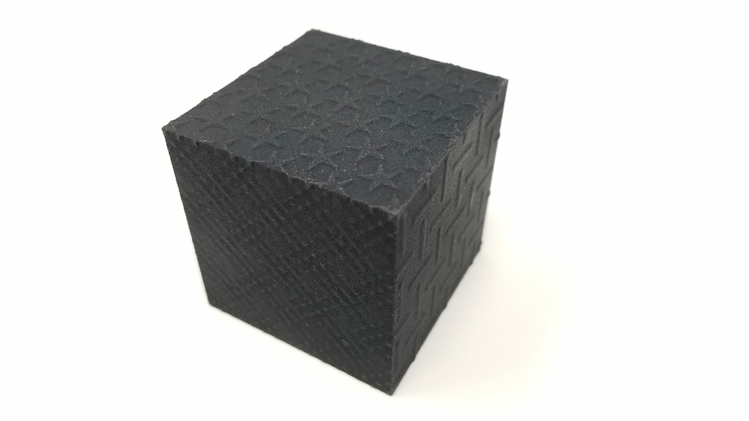
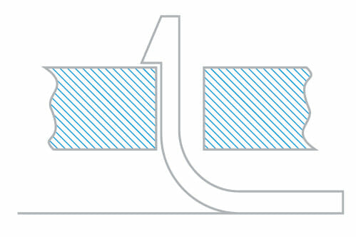
Moving on. Next up is FDM. This is a 3D printing technology that most people are most familiar with. This is your MakerBots. This is your Fortuses, your Dimensions, all the Stratasys equipment. It’s essentially a CNC-controlled hot glue gun. You run your ABS wire or PEEK or nylon or whatever material in and you’ve got a hot end and it’s going to lay down like white support material and it’s going to lay down black model material. The nice thing about these machines is they can get extremely large. A Fortus 900, off top of my head, I think it’s like a 24-inch by 36-inch by 36-inch build volume. You can get extremely large with these parts and it’s an end-use thermoplastic. I see a lot of people using these for either big injection mold parts like we’re in Western Michigan, so automotive, big interior dash components, headliner components, outer trim, bumper components, things like that.
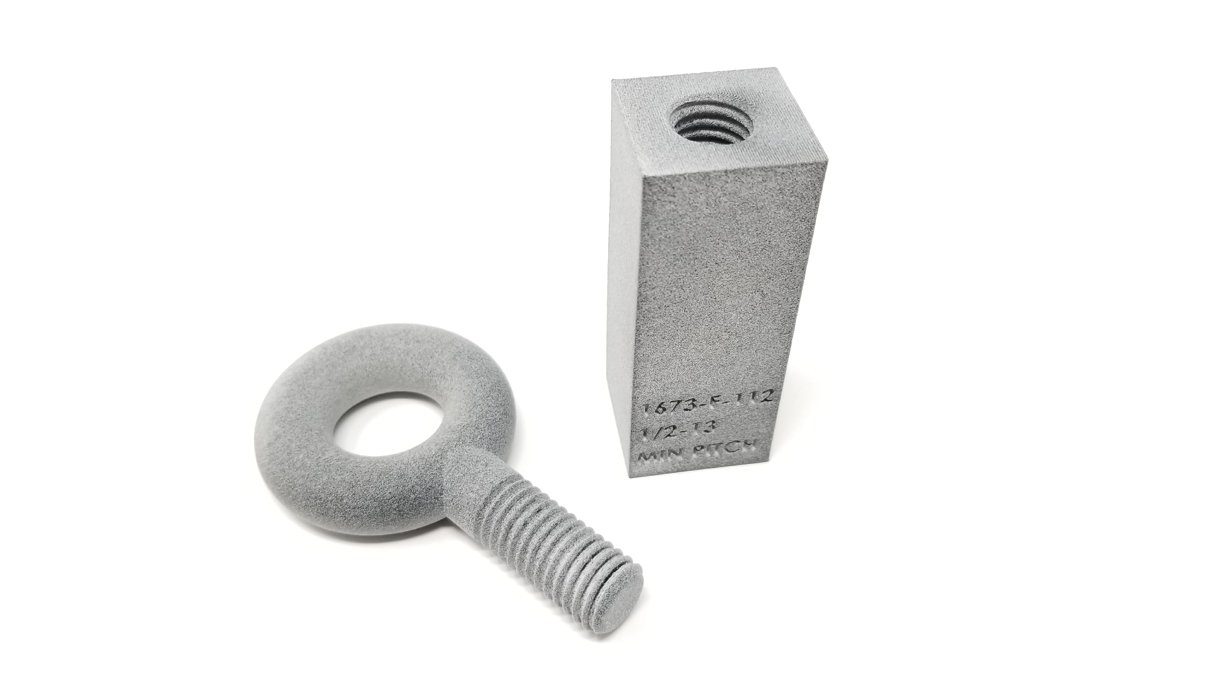
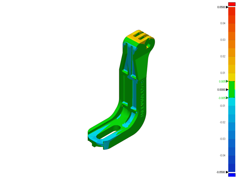
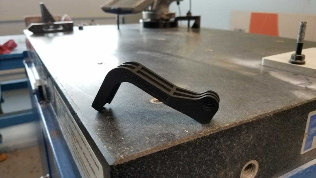
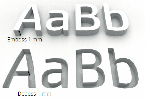
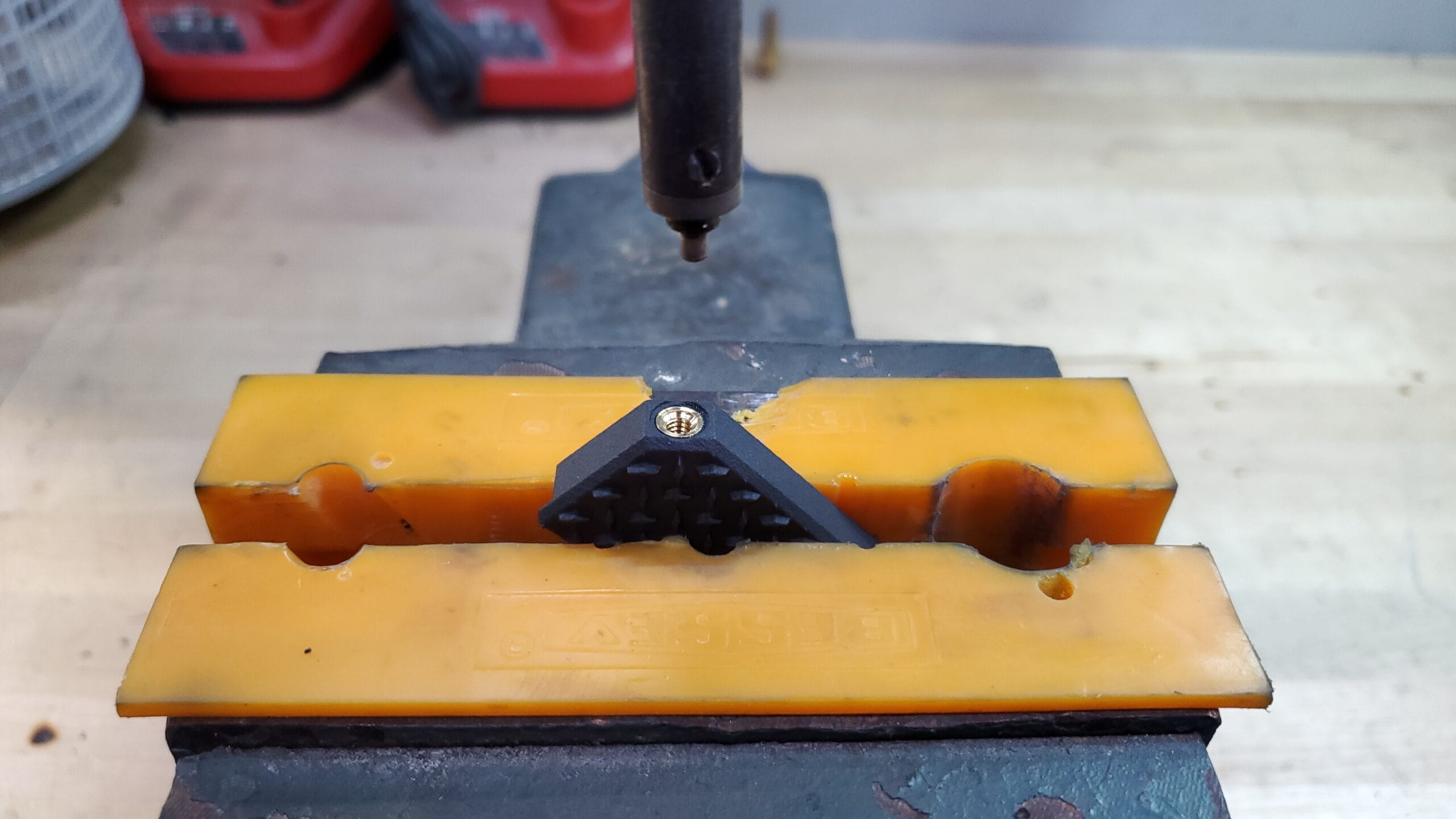
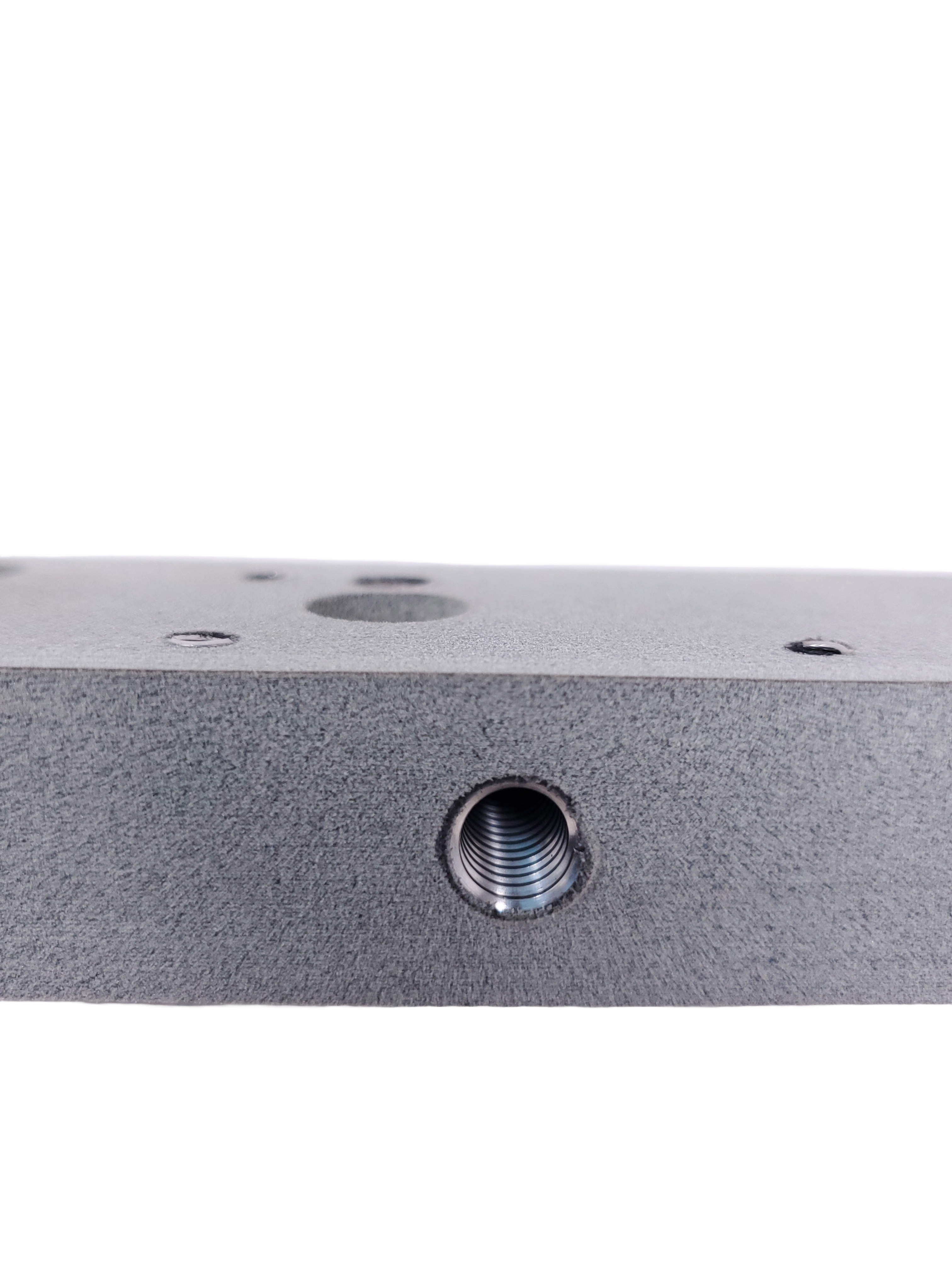
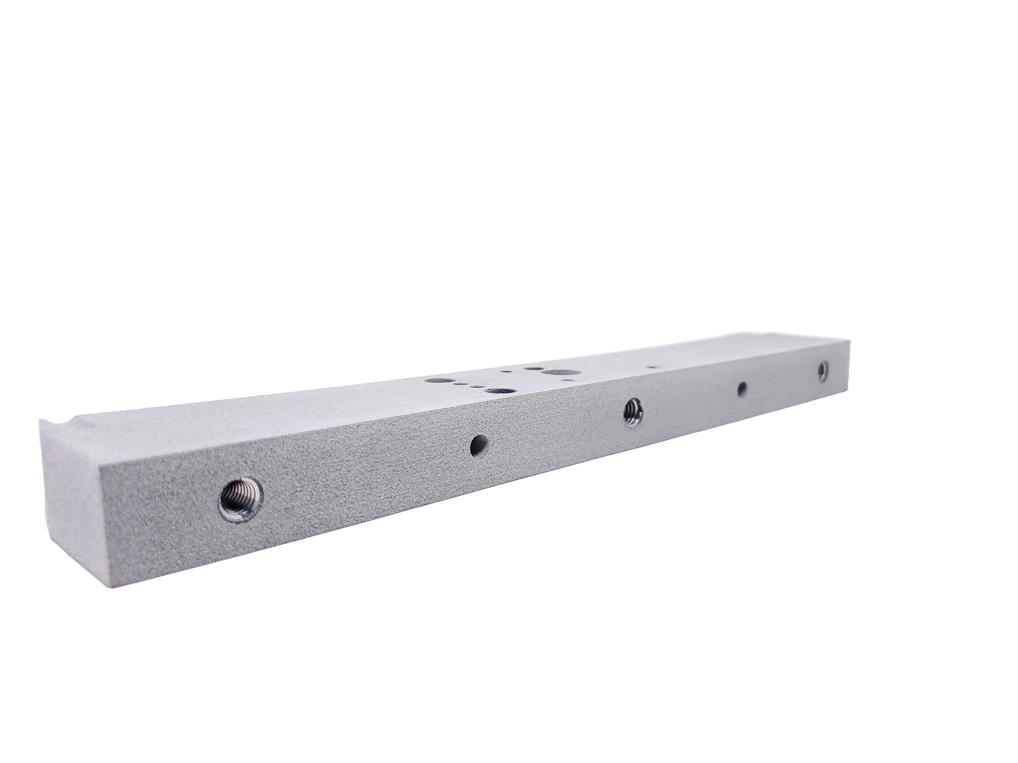
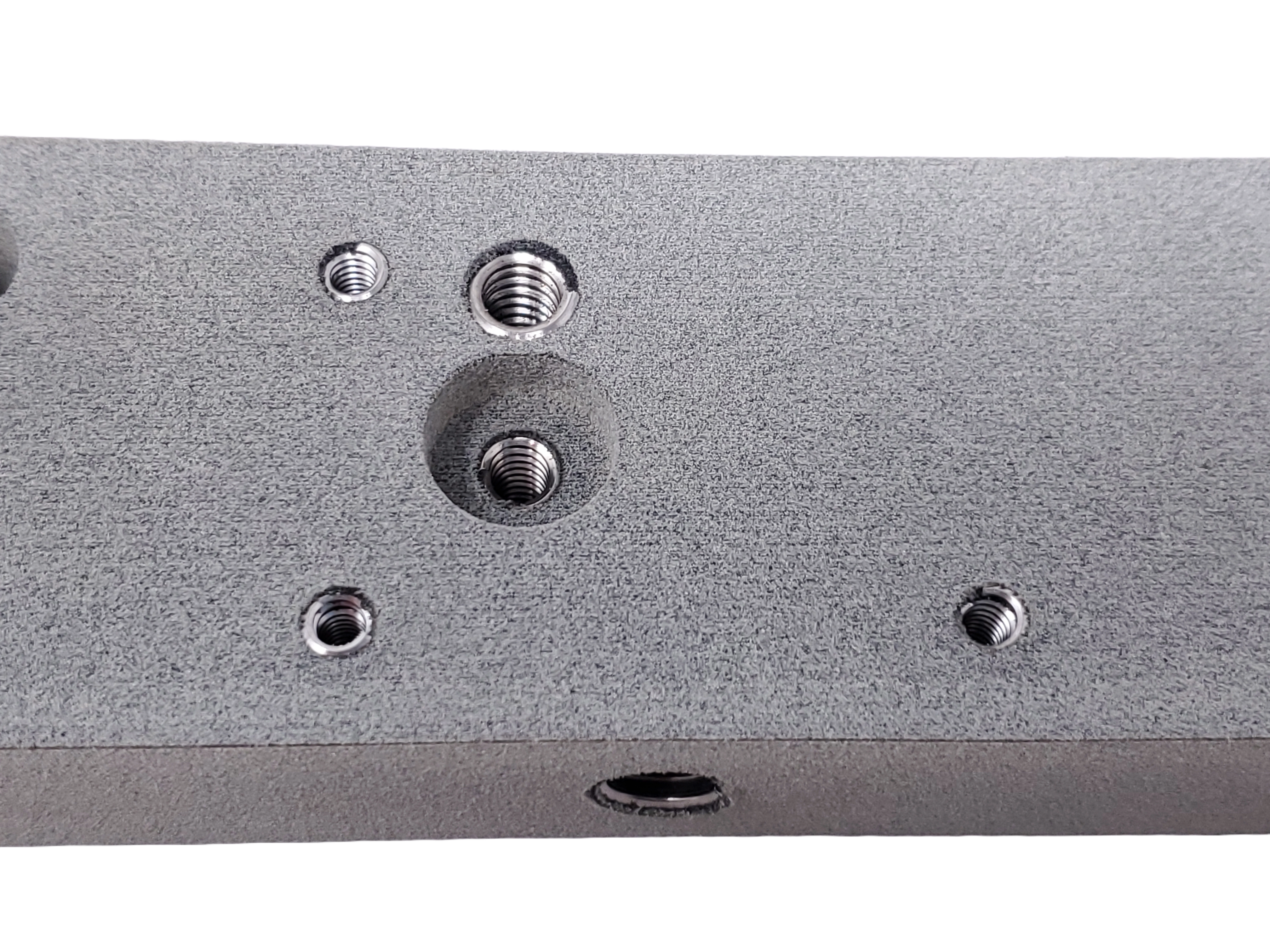
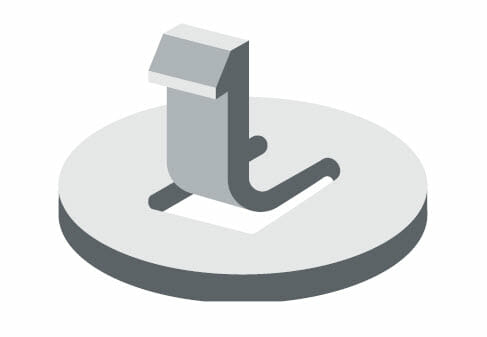
A lot of med device companies may use it for large like hospital beds and things like that, but also a lot of tooling, so a lot of vacuum forming tooling. People will use this instead of a red board, CNC-milled red board tooling, just all kinds of applications for FDM. Again, one of the older more legacy technologies, but still very actively used today. This is a specific example of one of our parts here. Example, tape applicator hand tool. The challenge, design and 3D print a series of ABS plastic hand tools that can be used to guide the application of tape onto windows during assembly. The tools are used on a daily basis and need to be strong and were resistant. There is a large range of window sizes and designs. That coupled with the cost to set up CNC machines for each size tool require the need for the finished cost of the tool to be $100 each. That just made traditional CNC machining just too expensive. The mix was so high and the volume was so low that they just couldn’t get their prices that low. All of this was literally done. This wasn’t done on one of our big Fortus machines. This was all done on like a desktop 3D printer. Something that I’m sure a lot of you have in your offices, a Markforged, an AXIOM, a MakerBot. That’s what we do all these on because the price is so low on the materials. I want to broke it. There we go. The upper right hand picture, that’s actually the finished part right there that I’m going to be talking about, and then, the rest is the SOLIDWORKS model showing how the part actually goes together. Again, different 3D printing process, but you still have to think about adding clearance around components that are going to be trapped inside of there. Now in this case, it’s this blue roller which is actually colored white up here, making sure we have enough room inside of that pocket for that roller to sit in there and not be tight and not get bound up. For FDM, we generally leave about 25,000s around the exterior part of mating components to make sure there’s plenty of room for them to run smoothly inside of there. Allow for … Let’s try that again. To allow for the nice round holes that you need in a lot of situations, you always want to try and orient your critical holes straight up in the Z direction and this applies for actually any 3D printing technology out there but specifically for FDM. If you have a hole that’s on its side, so the machine is building support inside the hole and that’s what’s creating the whole feature, it’s always going to come out egg shaped. It’s never going to be perfectly round. If you want a perfectly round hole pointed straight up in the Z and it will be extremely round every single time. Otherwise, plan on thickening the wall and then running a reamer in there to true that hole up if you can’t lay it down and print it straight up in the Z. Let’s see here. Another design consideration here was you’ll notice that we have these big flat surfaces on the sides here. The reason for that is, again, support. In this case, this will print with zero support on our FDM printer. That means there’s no support to break off. There’s no support stubble to sand off. There’s literally no modelmaking time associated with this. It’s just putting the parts together when you’re done. By leaving a nice big flat, we get that zero support because we’re building it right to the print bed and also you actually get a really nice like high polished surface finish on those sides, which is where someone in this case is going to be gripping. They wanted it to have a nice smooth finish for people’s hands. You will wind up with a pretty nice burr around the outside when you’re doing FDM printing. Just run around it with a deburr tool. Zip that burr right off there and you’re done. Again, anytime you’re doing FDM printing or SLA printing, the bigger flatter surfaces that you can put down towards the bottom the easier the supporting and then finishing out the part is going to be. Let’s see here. Then lastly, these feed ramps, which is where the tape actually, double-sided sticky tape, goes through as we’re applying it to the windows, we wanted those ramps to be as smooth as possible. We didn’t want like a stair-stepping effect from the layer lines. Again, by orienting it this direction, the extruder is running along that edge right there, so your layer lines actually go in the direction of which the tape is going to be moving through there. If you have layer lines going across your direction of movement, you’re introducing friction into that movement, whereas if your layer lines go along it, it actually helps because you’ve got little air gaps in there and so you’re actually substantially lowering the friction by pointing your layer lines through the ramps of your parts, around these parts. Again, when you’re designing, think about layer lines and layer direction and there’s a new feature or newer feature in SOLIDWORKS here, I’m going to show you in a second that helps visualize that really well. All right, so 3D texture. This is a tool inside of SOLIDWORKS. If you go up to the little help window on SOLIDWORKS, you can change it to commands. You type in 3D texture, and boom, it will pull up the 3D texture tool because I don’t actually know where the button is to be honest with you. John, can you tell where the button is? I don’t know where the button is. Just search for it. That’s the best way to find it. If you play around with SOLIDWORKS rendering at all, you’ll notice that I believe at the very bottom of the tab for all your different finishes and colors and everything like that for real view graphics. There’s actually a textures button at the bottom. Inside that textures button, I think it might even be called 3D textures, there’s all these grayscale images sitting in there. For the longest time, I was always like, “Well, this is dumb. I can’t do anything with this. What’s the point?” Well, they introduced this tool. Now, you can apply these grayscale images and then use this 3D texture tool and you can actually texture apart. This is what it looks like in SOLIDWORKS with the texture applied. This is what it looks in SOLIDWORKS after you run the 3D texture tool. This is what the actual printed part looked like after we 3D printed it. Yes? The question is, by default, will the texture apply to the outside of the surface and not grow your part? No, the texture will grow your part. Good question. It will definitely make your part bigger. There’s a whole bunch of sliders and fun buttons that you can click in this toolbox right here that you can make the texture more aggressive, you can make the texture more subtle. General rule of thumb though for specifically HP MJF-printed parts, your texture has to be at least 35,000s tall for it to show up on your part. Anything less than that, it will be there, but it won’t look great. 35 thou and bigger, that texture will pop out really nicely. Do I see some other hands? No. 3D texture, very, very powerful. I highly recommend you just go and play with it. There’s some really good videos on YouTube of people using it. Definitely check this out if you’re trying to do anything cosmetic with your parts and you want to hide the traditional 3D printing texture. I would recommend against 3D texture for things like FDM-printed parts and SLA 3D-printed parts. I would stick to things like PolyJet, HP MJF, and SLS machines. The SLAs and FDMs, I don’t really think have the resolution to do this on a sidewall, maybe on a top surface, but definitely not on a sidewall condition. That’d be a vertical wall. This is by far one of my favorite things. Like I said, we do a lot of automated equipment. Literally last night I had a customer send me a part. It’s a little block and it’s meant to hook into at 8020, which is an industrial erector set for lack of a better term. We use 8020 for machine guarding. Anytime you walk through a factory, there’s all those nice big Lexan windows to keep you from reaching in and getting killed by a robot. That’s pretty much all 8020 or Bosch that is holding that together. This customer designed a little block to hook into the 8020 channel, and then, he put a 1/4 x 20 hole through the block. He’s going to use these blocks to attach Lexan to his machines in a very specific way where he couldn’t find a mount on the market to do it. I’m sitting there looking at it and he wants to order a thousand of these. That means we’re going to print a thousand of them. Then, one of my modelmakers is going to sit there for like a week with a hand tapper, like a hand tap and tap a thousand holes into these parts. Again, it drives the cost way up. Before we knew that we were going to need to tap these, it was like a $3.50 part. Then when I found out that I was going to have someone sit there and tap all these holes, it jumped up to a $6 part. What we’ve found over the last couple years is when you combine Hole Wizard and the Thread Tool inside of SOLIDWORKS, you can print threads. Now specifically, we always do it on our HP MJF machine, that nylon machine, but we’ve also done it a little bit on FDM and a little bit on SLA and a little bit on PolyJet. It does work on other technologies as well. You can’t go under a 1/4 x 20 in thread size or an M12 in metric thread size. Anything smaller than that, unless you’re running a PolyJet machine, you just don’t have the resolution to resolve those threads, but with a 1/4 x 20 and up you can print the thread directly into your part. With HP specifically, it’s insanely strong. This is a test block that we have right here. We put onto our pull tester. So that’s a 1/2 x 13 thread size. That’s literally an eyeball downloaded from McMaster-Carr. They already have the threads on the outside of it. Then, we pull up the Hole Wizard. We put in a 1/2 x 13 tap drill size into the block. Then, we grab our Thread Tool. Again, there’s a bunch of great YouTube videos that will walk you through how to use the Thread Tool way better than I do up here in front of you. I highly recommend look up how to use the Thread Tool on YouTube. You run that thread down in there, and then, you actually print the thread. This thread right here, this broke at over 900 pounds intention and it wasn’t the thread that actually pulled out of the block. The eyeball actually broke where the cross section neck down at that first thread. We were able to take a punch and spin the broken portion of the thread out of that hole and put a fresh one in there. It didn’t elongate the threads or anything. When you’re using the correct 3D printing equipment and you’re printing threads, they can be insanely strong. Thing to keep in mind though is if you’re running a metal fastener into a plastic thread and you’re taking it apart and putting it together, over and over and over and over, eventually you will wear those threads from metal and plastic contact. The hack there is if you can, use a plastic fastener. Again, you go to McMaster-Carr. You can find tons of plastic fasteners, and if you have an application where you don’t need a ton of strength in your fastener, you’re just trying to hold something together, you can use a plastic fastener on a plastic 3D-printed part and those threads are going to last you forever. That’s a really fun SOLIDWORKS trick too is use Hole Wizard plus Threads and you can unlock some really cool design capabilities. This is another new one that we started playing with this last year, ran into … How are we looking on time, 10 minutes? Thank you, sir. What we ran into last year is we’ve got customers now that are designing specifically for end-use additive. What happens all the time is people will go, “How big is the machine?” You go, “Oh, it’s 15 x 12 x 15, or in the case of like an SLA, it’s 20 x 20 x 20.” Inevitably, they will design a part and it will be just a hair too big to actually fit into the machine without fail. Inside of SOLIDWORKS, I think this has been around a couple years, but they have this 3D print button. If it’s under file and 3D print, if you’re in the part, working tab. If you go there, there is a little 3D printer simulator. I had a customer told me about this actually and I first heard about it, I’m like, “Oh, great, so it’s going to have every type of MakerBot and every type of FormLabs and none of the stuff that I actually use.” Shockingly, they have a massive list of 3D printers. All of the ones I use are in that list. What you can do is up here at the top, I have this set to HP Jet Fusion 3D 4200. That’s the full name of our MJF system. Then, it sets the bounding box, and then, you can actually show your part inside the bounding box of the machine. As obvious as this sounds, this is massively helpful for people to your question who are new to 3D printing, who don’t necessarily know sizes off the top of their head. This is a great way without having to call your service bureau to figure out what size machine you’re actually … If you know what type of machine they’re going to run it on, you can check to see if your stuff’s going to fit even before you send it to them or you might have a conversation with them like I did with this customer of, “Okay, it’s pretty tight side to side, but if we tip it up 20 degrees, it’s going to make your part a little bit more expensive, but we can fit it in the machine without having to add cuts or splits or anything like that.” This is a really handy tool for just quickly analyzing, “Will something fit? Will something not fit?” Now, remember a couple slides ago, we’re talking about FDM. We’re talking about having your layer lines in there and trying to figure out what direction your layer lines are going to go in because you want a smooth layer lines in one direction. You can actually turn on layer height and show striation lines and it will actually put a texture onto your part. You can see what the layer lines would look like and how those lines would be oriented depending on how you have that part sitting in there. I’ve shown this to a number of customers. Now instead of just getting a step file and a quantity and a material, a lot of times I’m getting, a picture as well from the customer saying, “Hey, I really want my layer lines oriented in this direction.” This is a super easy way to start that conversation between you as the designer and engineer and whoever’s running the machine, whether it’s your internal guy running it or an external service bureau. This is a really, really handy way to visualize what those layer lines are going to look like and also to the cosmetic question about wanting to apply textures or something like that. Again, if you’re like, “How’s this part going to look with layer lines in it as opposed to a texture?” this is a great way to simulate that without having to actually get the part printed and then not be happy with the finish. Because again, if you can tell your 3D printing company, “Hey, don’t worry about sanding out all the layer lines. I’ll just take it as is,” you just cut your price by probably 25%. Well, that takes us to the end of my presentation. I’ve got a couple minutes left. If anyone has any questions, feel free to raise your hand.
Place Holder