At Forerunner 3D Printing we currently producing HP MJF 3D Printed Parts that are made out of Nylon PA-12. They feel strong when handled, and the material spec sheet from HP says they are strong as well. We have had early success with using them in high load applications that required them to be strong however, we needed to produce our own evidence of MJF part strength as well as MJF part wear resistance in order to convince some of our customers of its viability in their applications. In order to accomplish this we handed the parts over to our sister company DeWys Engineering, and they designed a few tests that could show the true strength of MJF 3D Printed parts in various scenarios. The following are our independent testing results based on real world applications we have considered using MJF 3D Printed parts for. We plan to continue updating this page as more of our testing is completed. If you have a specific application you would like to see tested, let us know we would love to talk with you about it.
MJF Part Wear Testing: 3D printed nesting application
We have seen quite a bit of interest from various machine builders we work with around using MJF components as nesting details for holding components in place while they are assembled on automated / manual factory equipment. After presenting them with example nests the first questions that they asked was “how wear resistant is this Nylon PA-12 material”? Handing them a spec sheet and telling them to trust us was not going to cut it. The next step for us was to do some testing to prove out its wear resistance and that it could hold up to abuse as well as a traditional nesting that was machined out of Delrin or Nylon.

A purpose built MJF wear tester was constructed and the following test was run:
- Pneumatic air cylinder: The cylinder was hooked up to a 90PSI air source and was able to develop 100 LBS of force on its extend stroke as it drove the aluminum block into the nest.
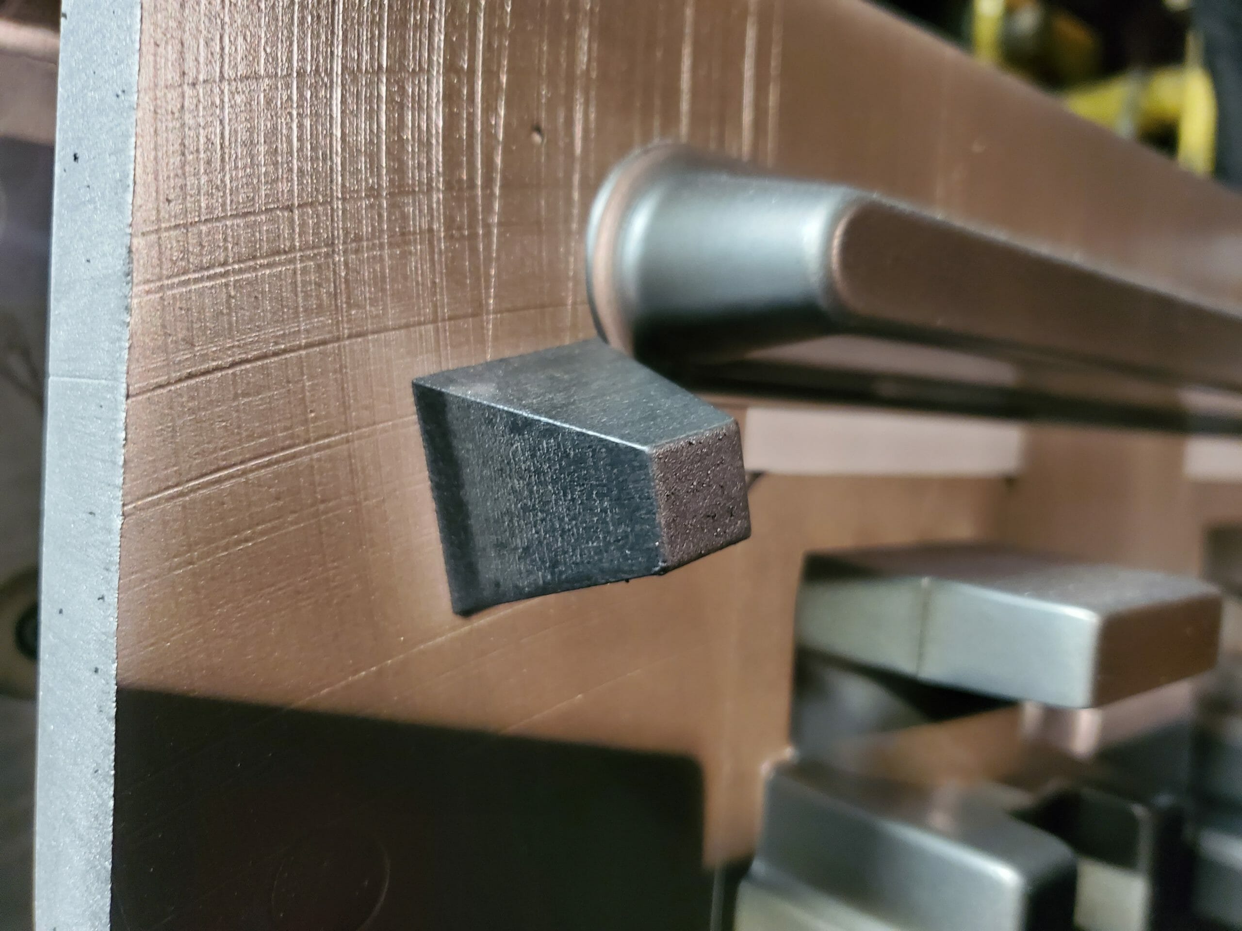
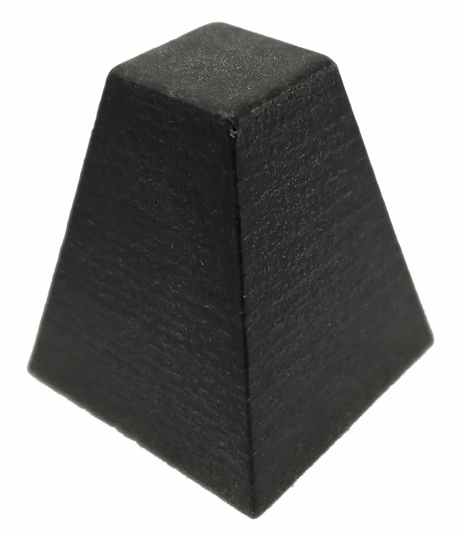
- MJF 3D Printed nest: Was bolted onto the base plate and had a .755″ wide slot that was meant to nest the aluminum block
- Aluminum block: Built to be .75″ wide, this detail is meant to simulate a part that is being repeatedly inserted into the MJF nest, over time it will likely cause the MJF part to wear
- .010″ shim stock: This is meant to cause a misalignment between the aluminum block and the MJF nest it is going to be placed in repeatedly, the hope is this will cause a wear condition
- Cylinder stroke counter: keeps track of how many times the Aluminum block has been inserted into the MJF nest detail

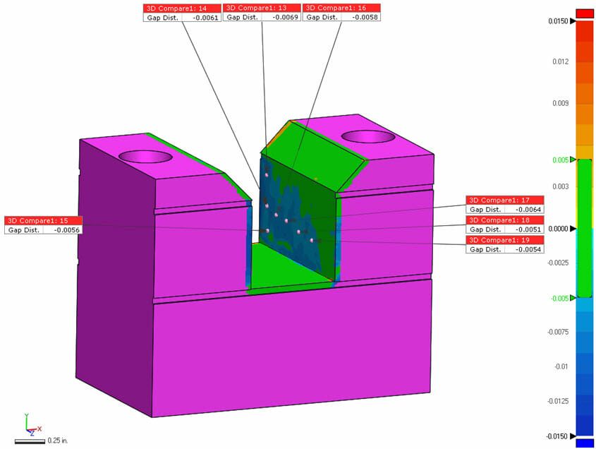
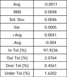
The end result of the testing was that the block showed some signs of highly localized wear up to .011″ but overall the MJF part wear was not as extensive as was originally anticipated. As a result, Forerunner 3D Printing is now producing nesting details for several of our machine build clients on our HP Multi Jet Fusion 4200 3D Printer in Nylon PA-12.
MJF Part Wear Testing: gripper finger application
MJF Part Wear Testing: Foundry tooling application
After being sandblasted 13,000 times in a DISAMATIC foundry mold production system test parts showed minimal wear, for a full write up on this test please visit our Foundry tooling page.

MJF Part Strength Testing: 3D printed thread / part tensile strength
One of the first questions we got from a potential customer was “how well do these 3D printed parts hold threads under tensile loading”, we did not have a good answer for them so we decided to find out! This testing also dovetailed nicely into a broader question around MJF part strength in general so we combined the two. We printed 1/4″-20, 3/8″-16. and 1/2″-13 test bars with threaded holes in either end. We then printed corresponding MJF eye bolts with the appropriate thread size on them. After putting them together we placed them in out tensile testing rig and gave them a pull! Here are the results:

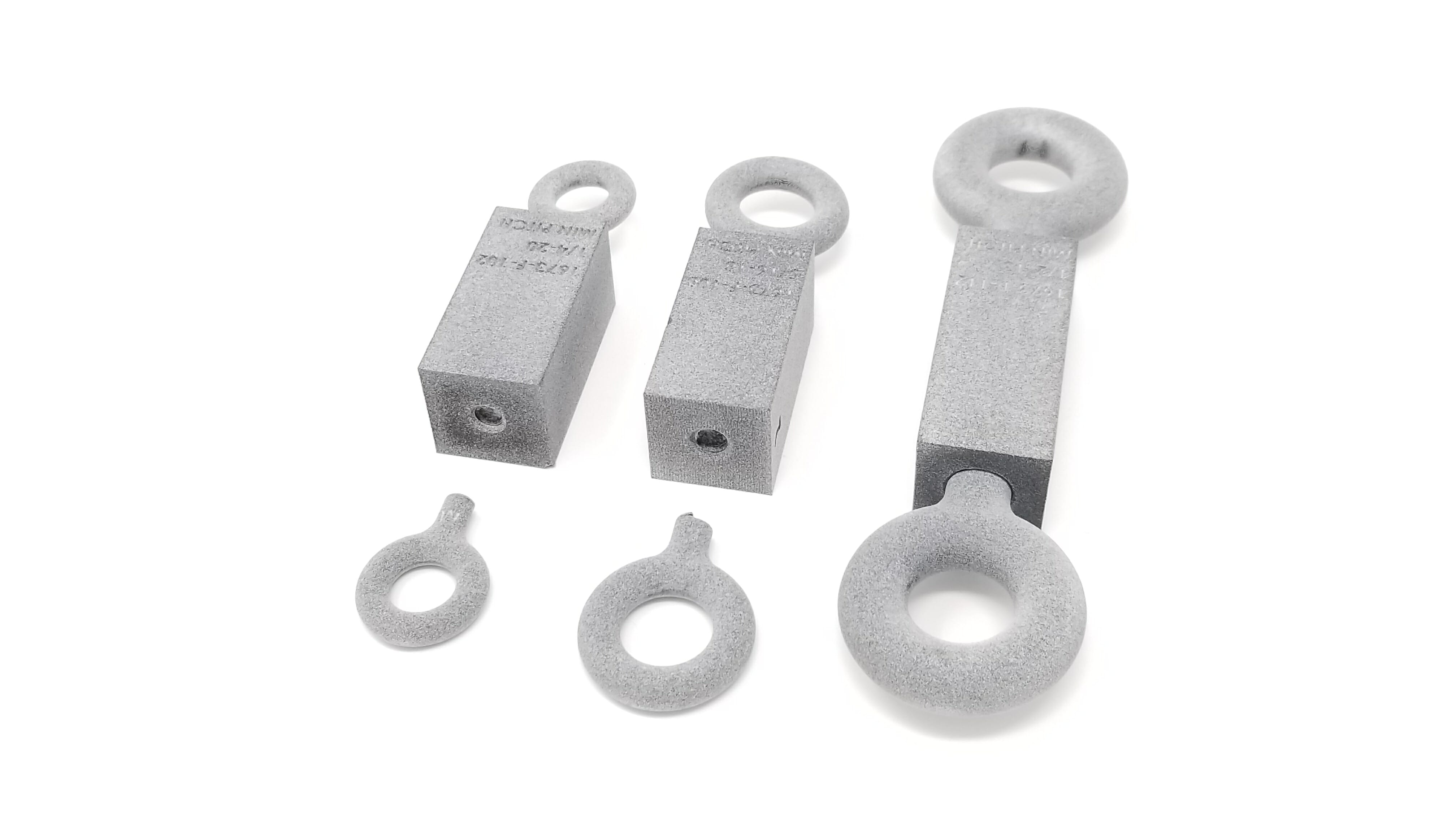
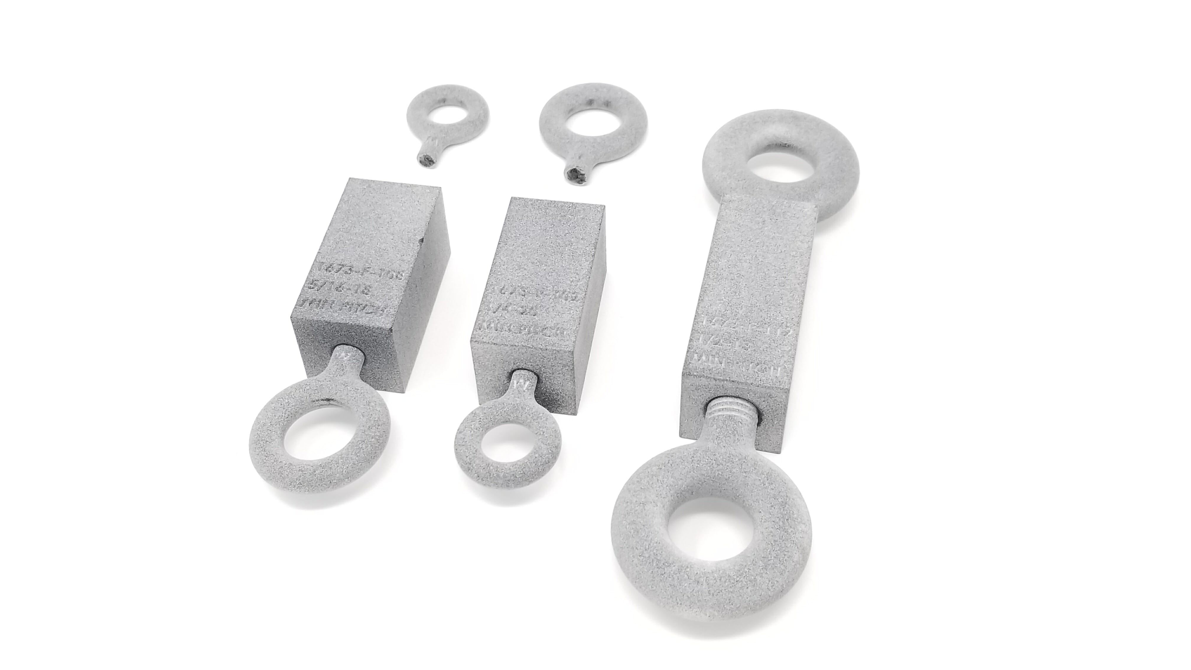
The breaking point for each sample was:
1/4″-20 = 211 LBS
3/8″-16 = 345 LBS
1/2″-13 = +650 LBS (part did not break, threads showed no sign of elongation or binding after test)
MJF Part Strength Testing: Sonic welding insert & pull out strength
When working with a customer who does injection molding the question was raised if MJF parts could have inserts sonic welded into them. We took the CAD data for an existing product that they currently injection mold and 3D Printed it on our MJF machine. The parts were then inserted with a 10-32 threaded insert on the same sonic weld machine that is currently used for production of the injection molded part. Here are the results of the MJF sonic weld trial as well as a follow up head to head pull test to determine MJF part strength vs injection molding.
MJF Part Strength Testing: Honeycomb structure pull test
A customer evaluating the potential of producing an end use part using MJF wanted to know how strong a honeycomb structure would be when printed. A test part was developed and pull tested by hand, here are the results:
MJF Part Strength Testing: Pull test in tension and shear
A machine builder had an application that required a hook that was potentially going to be made on our MJF machine to function under a load that was both in shear and tension. We devised a method of applying these loads to the test part and then produced both the test hook and the fixture to hold it with our MJF machine. Here are the results of that testing:
MJF Part Strength Testing: Glue joint strength and wear testing
A customer requested to know how well our standard glue joint would hold up to repeated shock loads. We devised this simple test to prove out the strength of a HP MJF glue joint as well as do a metal vs Nylon wear test at the same time. Here are the results of that testing:
MJF Part Strength Testing: Break Press Tooling Strength and Wear Test
We wanted to see if using 3D Printed Nylon break press tooling was effective for forming Aluminum and Stainless Steel parts while preventing them from being marked during the bending process. This also acted as a perfect test of putting the 3D Printed part under many tons of pressure and seeing how it held up from a wear perspective. We found the Nylon 12 part was non marking and did not damage the Aluminum or Stainless Steel test plates, it also held up great to the extreme pressures involved in the forming operation:
MJF Part Strength Testing: M16 Machine Gun & Suppressor Wear / Heat Testing
In our never-ending quest to torture test parts printed in Nylon 12 on the HP MJF 3D Printer an idea was proposed. Could we print a lower receiver and run it as a machine gun? What would happen if we printed the baffles for a suppressor? Behold the answers to these questions!
Interested in learning more about our work with the Defense and Firearms industries? Check out our dedicated page on this topic here.
MJF Part Strength Testing: 3D Printed Air Intake Manifold – Dynamometer Testing
We had the opportunity to help out the Saginaw Valley State University Formula SAE team with a additively manufactured air intake manifold that would fit on the teams Yamaha YZF-R6 engine. We produced it with our HP MJF 4200 in Nylon 12. As a bonus we got to see how the manifold would hold up to being bolted directly to the engine block and run hard. The feedback from the team was:
“We ran it on the dyno without any issues, and found an increase of around 8 HP. The highest temp that the flange got to was around 140 degrees Fahrenheit”
Another test that was conducted to determine the heat resistance of the PA-12 material was to replace a cast aluminum air intake elbow on a 5 HP generator with a laser scanned and 3D printed copy. The replacement elbow bolted directly to the side of the engine block and was subjected to temperatures in excess of 200 Deg F. The engine was then run continuously for over 100hrs and the 3D printed part held up without any issues.